






Project brief
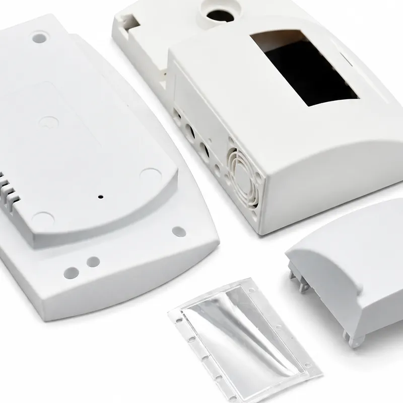
This representative case covers a transparent cover for an optical sensing module. The part protected an emitter and receiver while forming the visible front surface of the device. It therefore had to satisfy several requirements at once: optical transmission, low distortion, cosmetic quality, controlled fit, resistance to cleaning, and stable assembly. A clear molded part exposes defects that would be hidden in an opaque housing, so decisions about resin, gate location, polishing, drying, handling, and packaging all affect the final result.
The development plan began with the optical path rather than the exterior styling. HWPD’s engineering assistance process separated functional optical zones from surrounding cosmetic and fastening zones, allowing each area to receive appropriate tolerances and inspection criteria.

Why transparent parts require a different DFM approach
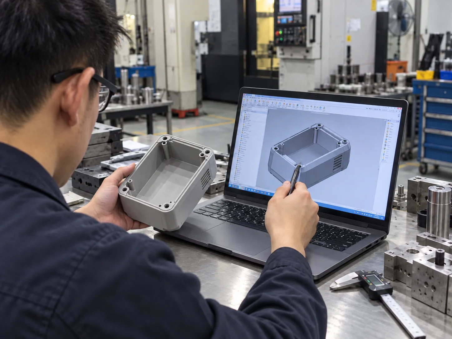
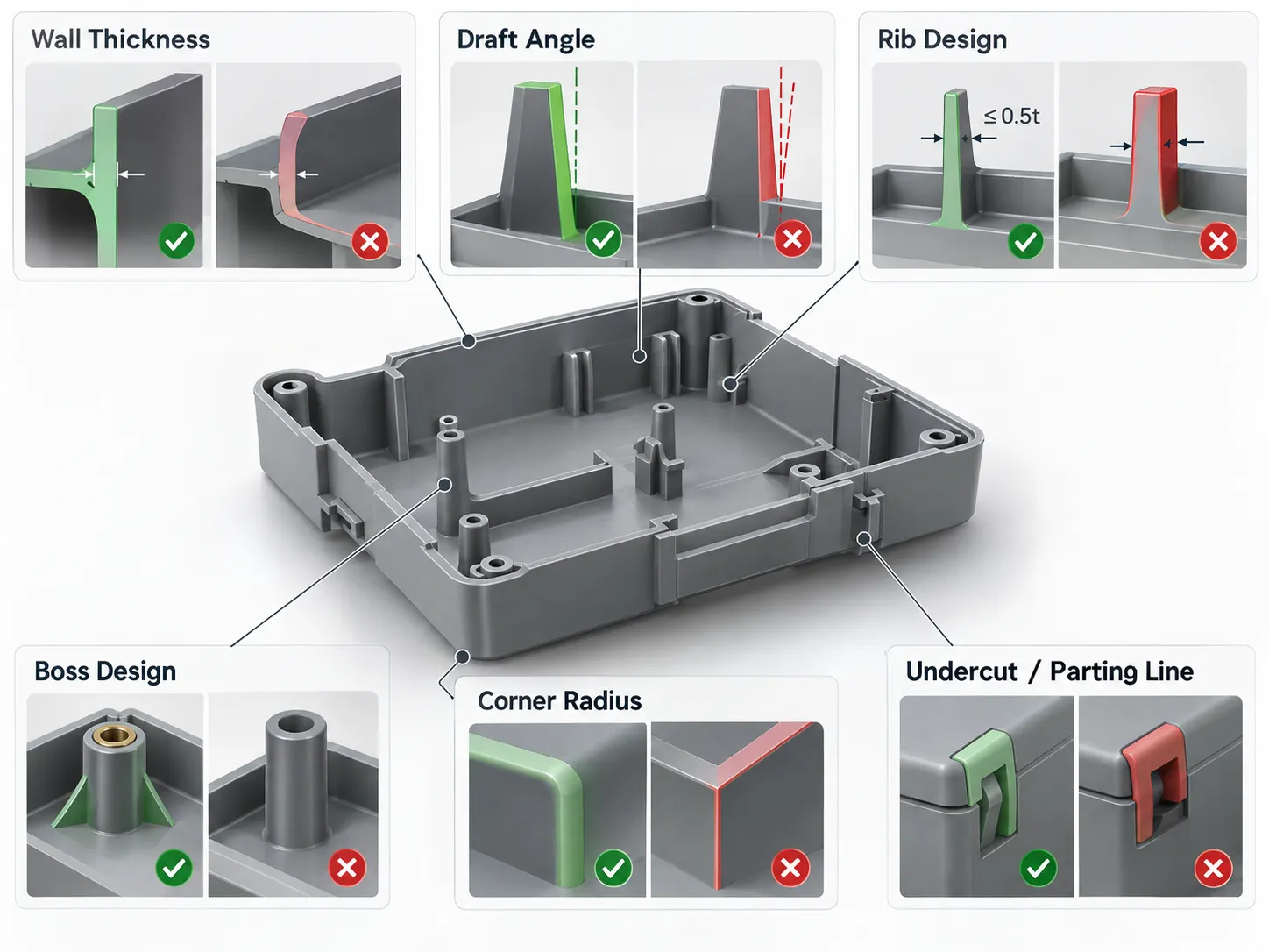
The first CAD model included abrupt wall transitions around mounting features and a gate concept near the viewing area. Those choices could create flow hesitation, weld lines, residual stress, and visible gate blush. A polished surface alone cannot correct stress created by poor filling or packing. Likewise, a dimensionally acceptable part can still fail if birefringence or haze interferes with the sensor.
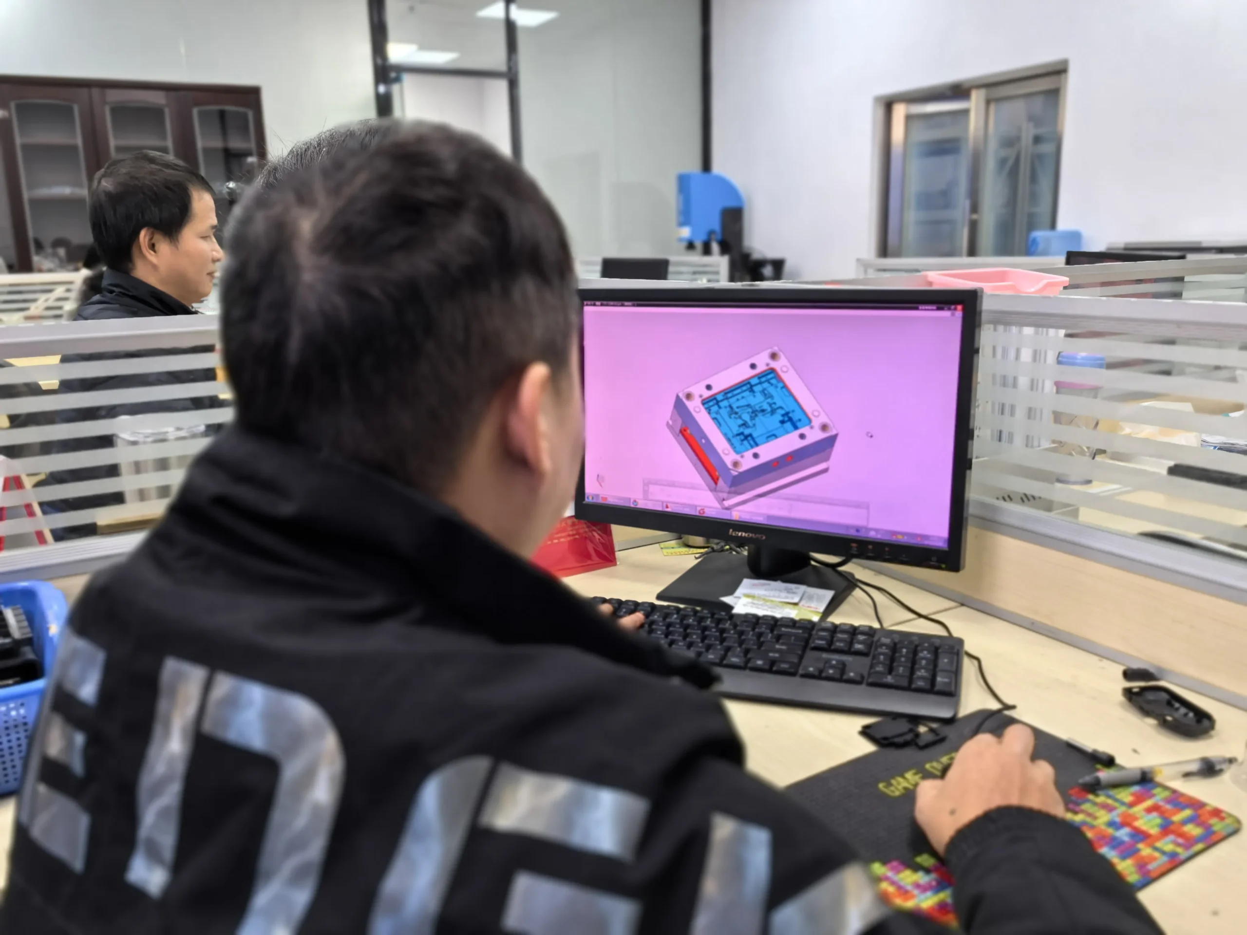
The DFM review simplified thickness transitions, softened feature intersections, and moved structural geometry away from the optical aperture. Draft was added without changing the required viewing cone. The parting line was routed outside the primary visible surface, and the gate was positioned so flow entered a non-optical region before moving across the cover in a predictable direction.
Material and prototype evaluation
Candidate resins were reviewed for optical properties, impact performance, environmental resistance, and processing sensitivity. Polycarbonate and acrylic each offer advantages, but the correct choice depends on the device’s impact, temperature, chemical, and optical requirements. Published supplier data and customer testing should determine the grade; a generic material name is not enough.
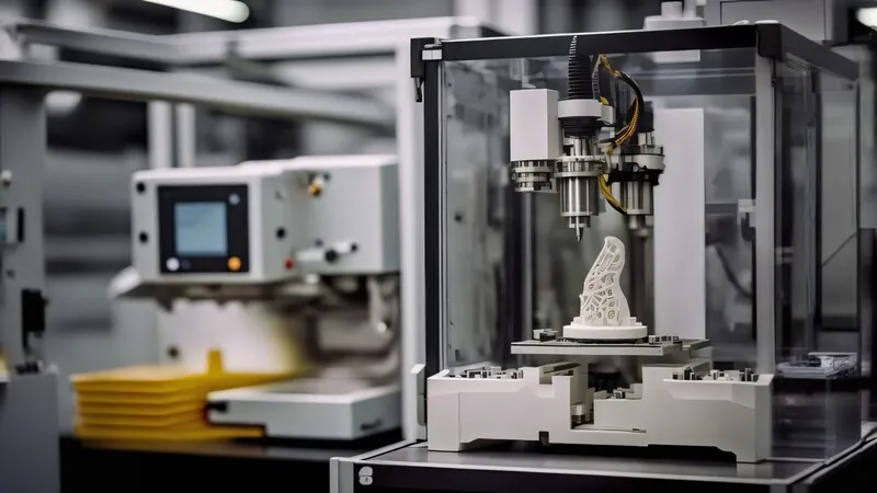
Early prototypes were used to verify sensor clearance, viewing angle, bonding land, snap engagement, and assembly sequence. Prototype optical behavior was treated carefully because printed or machined samples do not reproduce injection-molded flow orientation and residual stress. The team used prototypes to prove geometry, then reserved final optical acceptance for molded parts.

Mold construction for optical quality
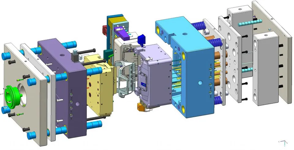
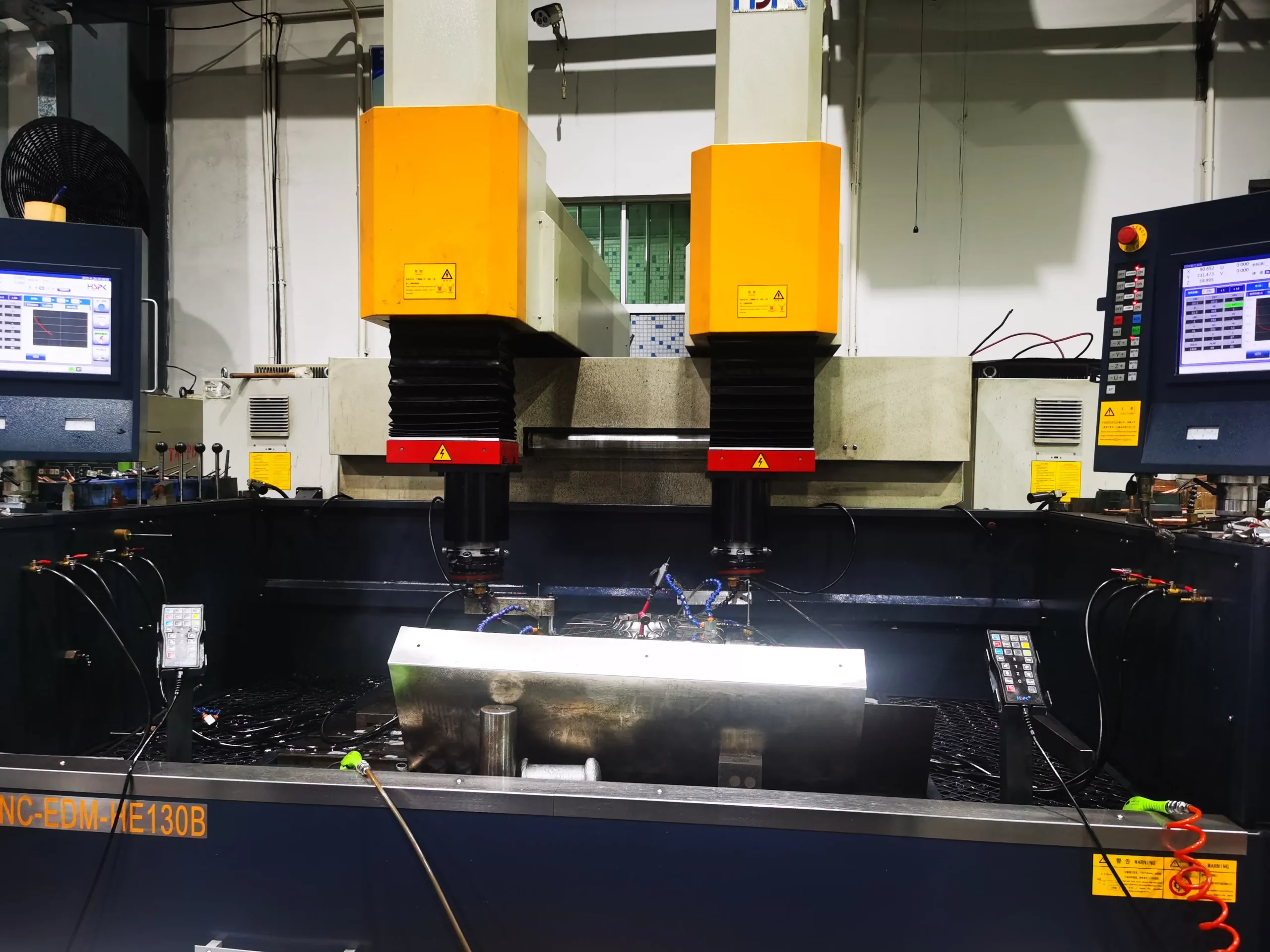
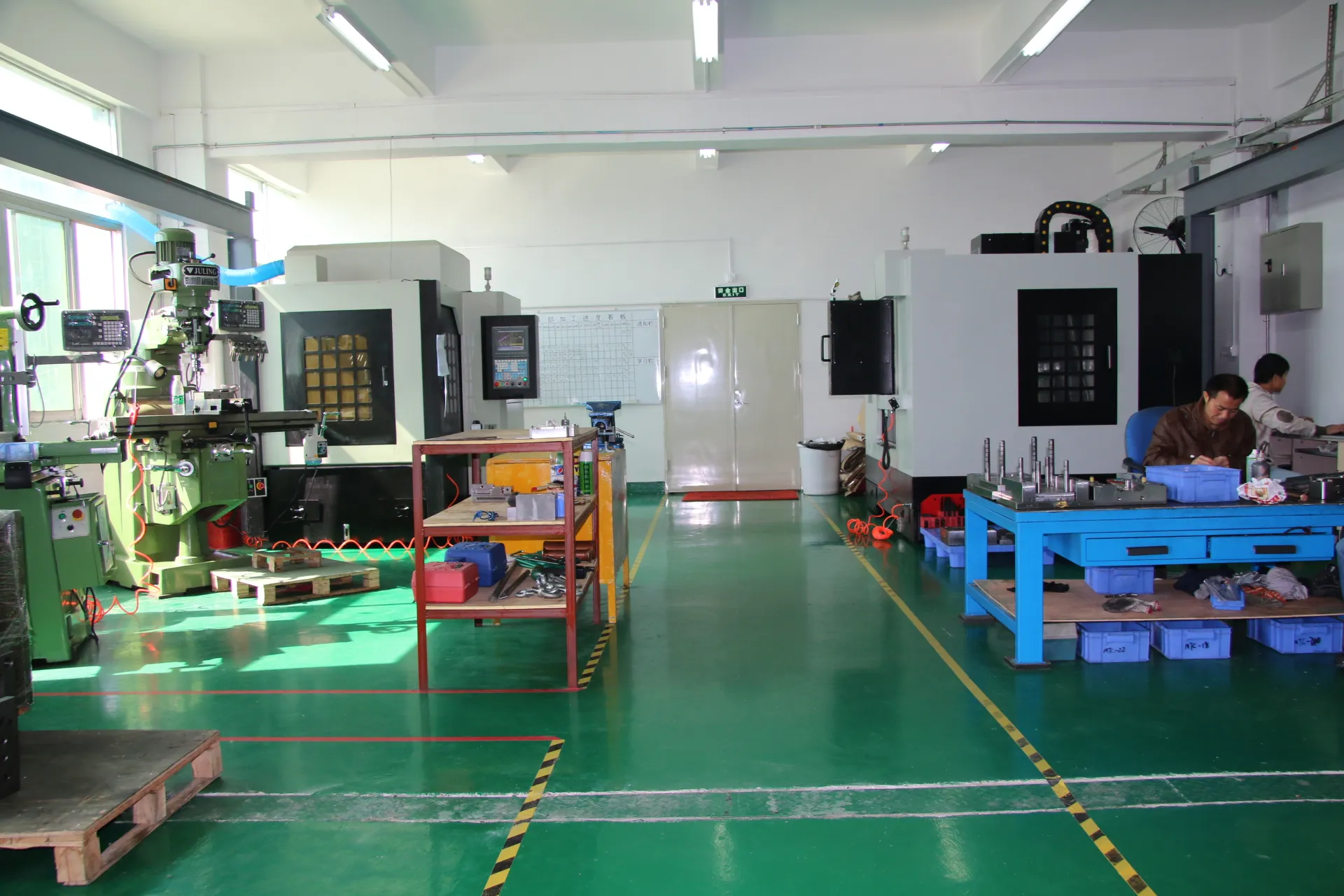
The cavity surface within the optical zone required controlled polishing and protection during tool manufacture. Steel selection, cooling layout, venting, gate design, and ejection were reviewed as one system. Ejector force was applied outside the optical area to avoid witness marks and local stress. Venting was designed to release trapped air without creating flash along the visible edge.
The mold manufacturing plan included inspection of the cavity finish before trial. Toolmakers avoided unnecessary hand work that could change optical geometry. Handling rules were established because fingerprints, polishing residue, and careless cleaning can be mistaken for molding defects.
Process development and defect control
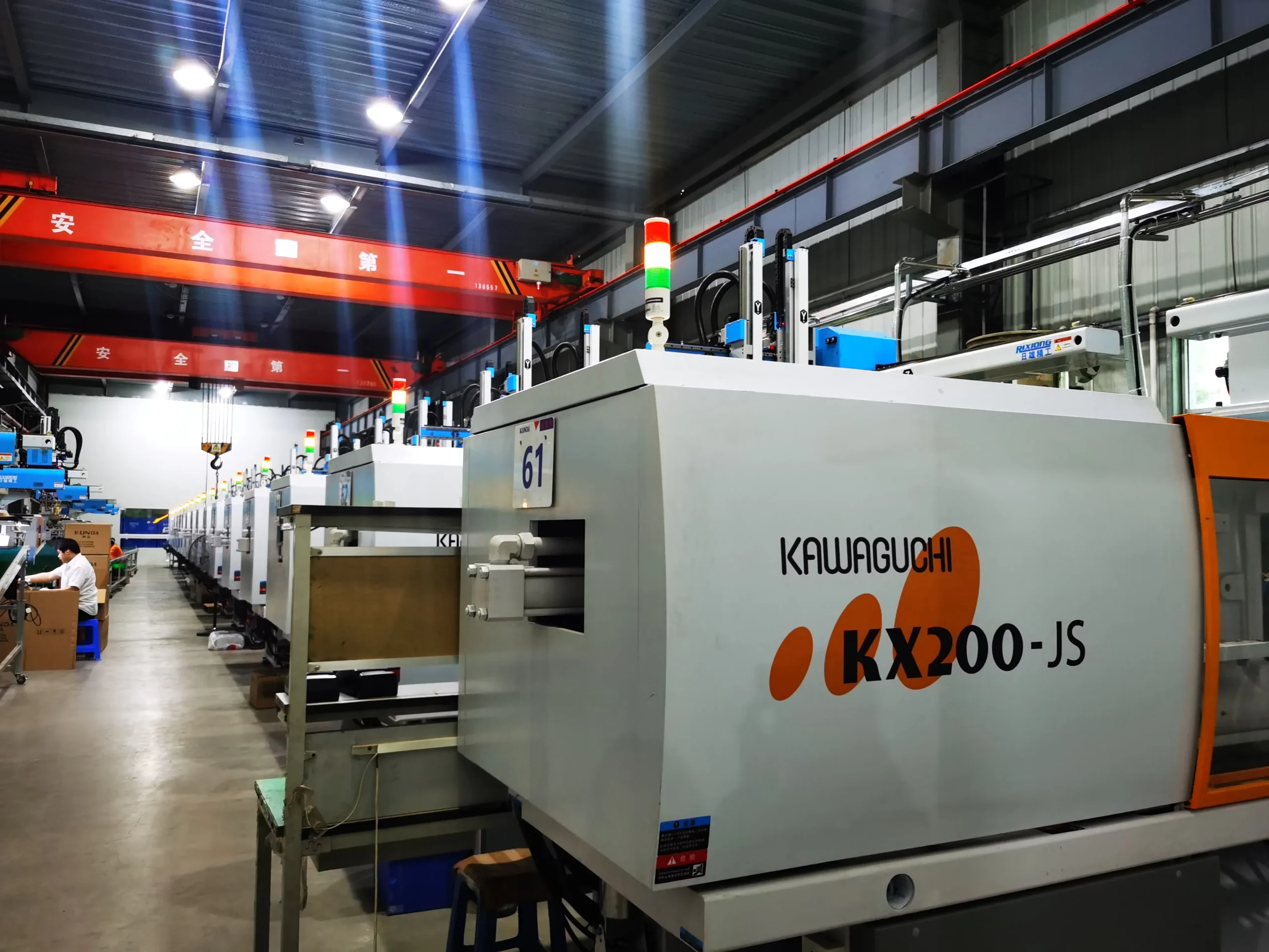
Clear resin demands disciplined moisture control. Material drying, residence time, barrel cleanliness, melt temperature, mold temperature, injection speed, packing, and cooling were documented during trial. The objective was a stable window, not one visually perfect shot. Excessive packing can increase stress, while inadequate packing can cause sink or dimensional drift. Fast or poorly controlled filling can produce splay, jetting, or blush.
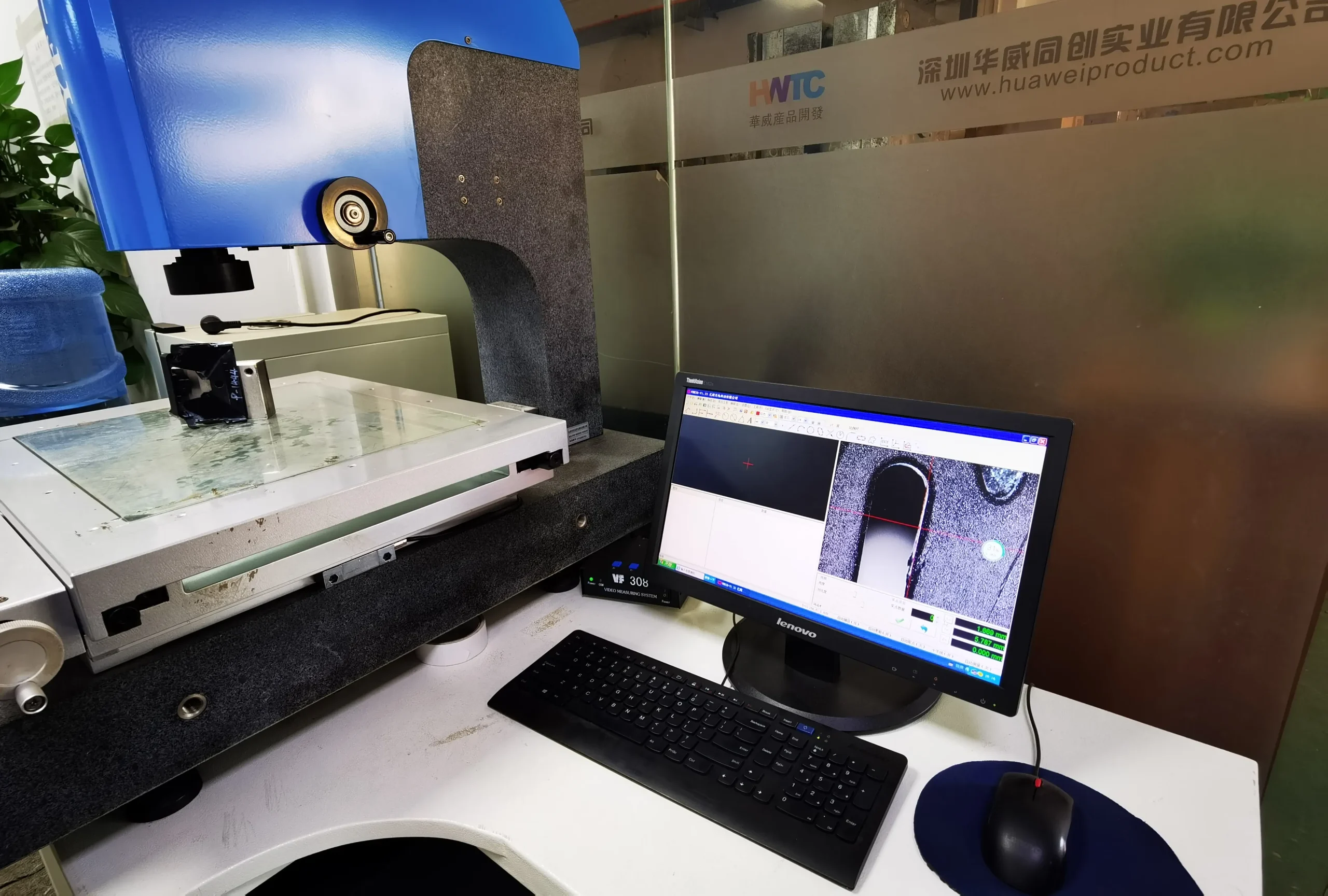
Inspection combined normal and controlled lighting. Cosmetic standards defined acceptable zones rather than applying one unrealistic criterion to the whole part. Optical areas were checked for haze, flow marks, contamination, and distortion. Polarized-light inspection can help reveal molded-in stress when it is relevant to the application. Dimensions governing sensor spacing and assembly were measured independently from cosmetic acceptance.
Assembly and packaging validation
The joining method was assessed for its effect on the clear part. Snap fits, screws, adhesive, and ultrasonic welding can all introduce stress if the joint is poorly designed. Assembly fixtures controlled part location and load. Cleaning materials were also verified because some solvents can trigger environmental stress cracking in transparent polymers.
Finished parts were protected with suitable separators or film and packed to avoid abrasion. The final control plan connected incoming resin verification, drying records, process settings, optical inspection, dimensional inspection, assembly checks, and packaging. For a clear component, quality continues after molding until the protected part reaches final assembly.
Release criteria and traceability
The release package distinguished optical acceptance from ordinary cosmetic acceptance. It defined the viewing zone, illumination, viewing distance, inspection time, approved reference samples, and the method used to assess distortion or stress. This kept subjective inspection from changing between shifts. Critical dimensions, cavity identity, resin lot, drying record, and molding parameters were traceable to each validation lot.
Any proposed change to resin, colorant, polish, gate detail, mold temperature, packaging film, cleaner, adhesive, or welding process required review for optical and stress effects. This disciplined change control was essential because a modification that appears harmless on an opaque component can become visible or functional on a transparent cover.

Outcome and engineering lesson
The cover became manufacturing-ready because optical requirements were translated into specific geometry, tooling, processing, inspection, and handling controls. The central lesson is that transparency is not merely a color choice. It is a functional requirement that changes the entire development route. HWPD can integrate these controls through mold design and controlled production.