We use necessary cookies to operate this website and optional analytics cookies to understand how visitors use our pages. Analytics cookies are used only with your consent. You can accept or reject them and change your choice at any time. See our Cookie Policy and Privacy Policy.


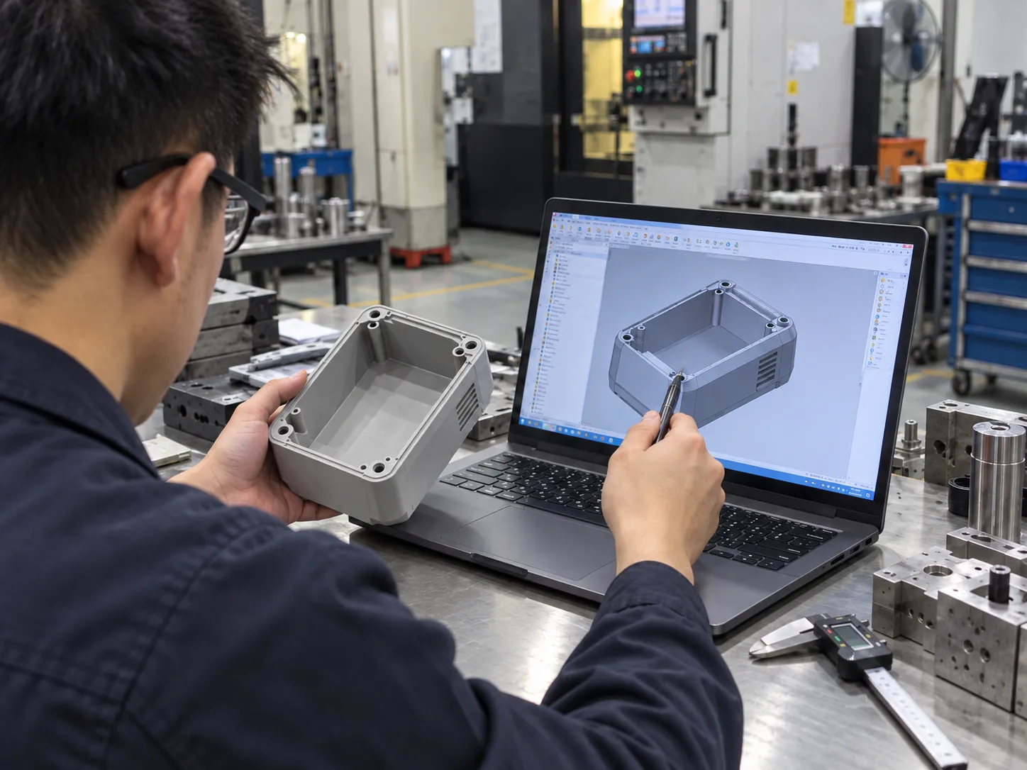
DFM analysis services from HWPD catch design issues before tooling — wall thickness, draft angles, gate location, undercuts, and tolerances are reviewed before steel is cut. Our Design for Manufacturability team helps optimize injection molded parts to save time, reduce tooling cost, and improve production quality.
Timing
Risks
CAD
Free
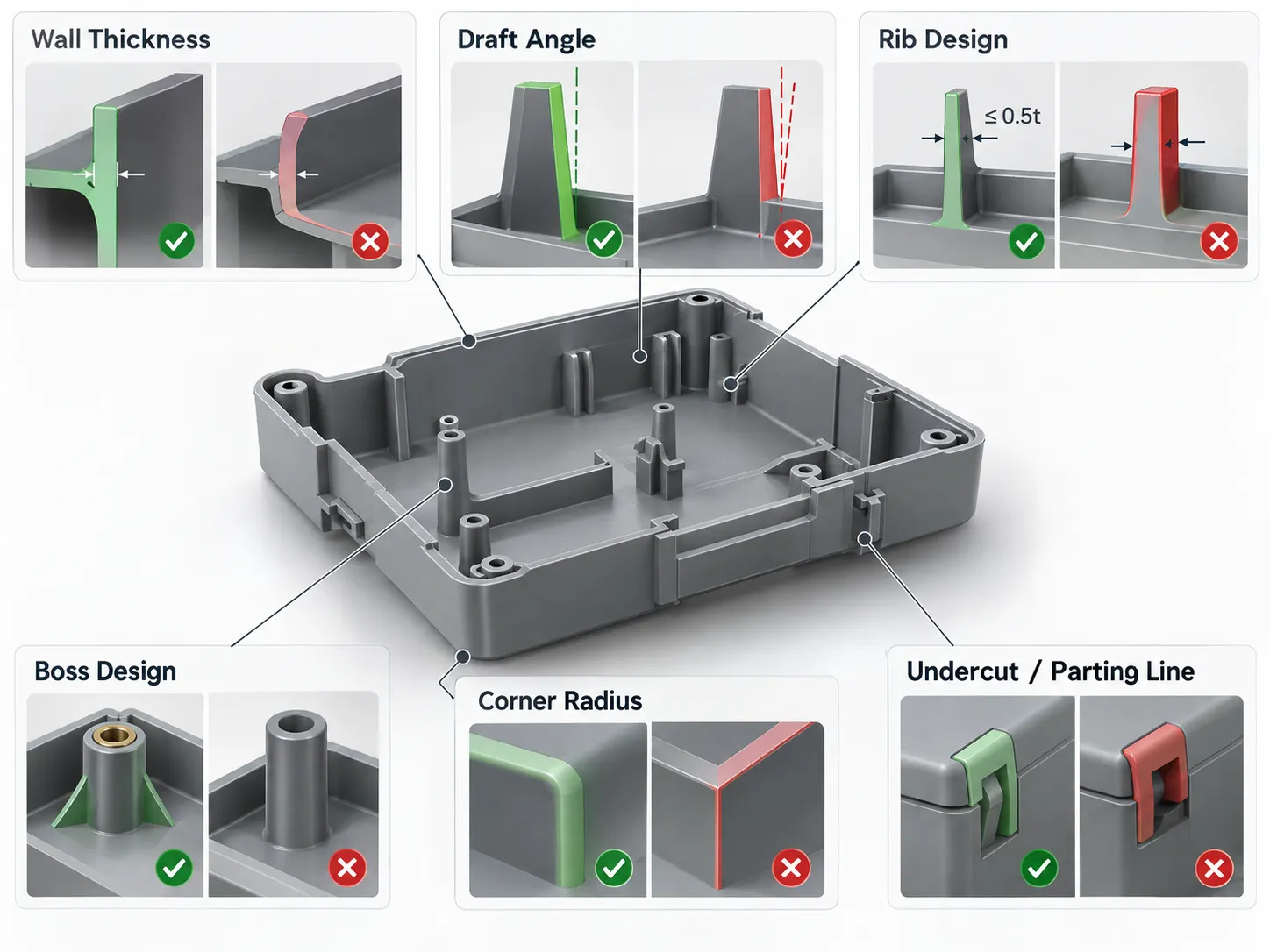
Our DFM analysis services review every critical aspect of your part design — from basic geometry and wall thickness to gate location, surface finish, and tolerance requirements. This Design for Manufacturability checklist helps identify costly issues before tooling starts.
For broader manufacturing quality references, see ISO manufacturing standards.
Timing
10+
Risks
Free
In our experience, most injection molded parts have at least 3–5 DFM issues that would add cost, delay production, or reduce quality. Our DFM analysis services identify these problems early and provide practical design recommendations before mold manufacturing begins.
Insufficient Draft
Vertical walls without adequate draft cause parts to stick in the mold, creating surface drag marks and mold damage.
Unresolved Undercuts
Hidden undercuts that require expensive slides or lifters — Some undercuts can be eliminated through geometry or parting-line changes, reducing slider/lifter complexity and tooling cost.
Wall Thickness Variation
Inconsistent wall thickness causes differential shrinkage, warpage, and can create shrinkage, warpage and sink that become more difficult and costly to correct after tooling.
Over-Tight Tolerances
Tolerances tighter than functionally necessary drive up scrap rates, cycle time, and tooling cost with no real benefit.
Gate Position Conflicts
Gates placed on cosmetic surfaces or near stress zones create visible marks and weld lines that compromise part quality.
Overly Thick Ribs Causing Sink
Ribs that are too thick relative to the nominal wall create sink marks on the opposite cosmetic surface.
Our DFM analysis services include clear, actionable reports designed to be understood by both engineers and non-engineers. Every issue is explained with a severity rating, the risk if left unaddressed, and a specific recommended fix for manufacturability.
DFM Analysis Services Report
Draft Angle — Section A (0° detected)
Wall Thickness — Rib-to-wall ratio 0.8 (rec. 0.6)
Undercut — Internal thread requires side action
Gate Location — Position acceptable
Material — Selected resin reviewed for wall thickness, draft, shrinkage and application requirements.
Tolerance Review — Tight requirement requires functional justification and process capability review.
A 3D CAD file (STEP or IGES) and a 2D drawing with dimensions and tolerances are ideal for Injection Mold Design. If you only have a 2D drawing or a physical sample, we can also create the 3D model and prepare the mold design package.
A typical single-cavity Injection Mold Design project takes 1–2 weeks. Complex multi-cavity or hot runner tools may take 2–4 weeks. We always issue a detailed timeline at the start of the project.
Yes. Mold flow analysis is included in our standard Injection Mold Design process for production molds. We simulate fill, pack, warp, and cooling to catch issues before any steel is machined.
Yes — we offer complete Injection Mold Design through to mold manufacturing and injection molding production. Design and build are handled by the same team, ensuring strong alignment between design intent and tool execution.
You do. Upon full payment, all Injection Mold Design files, 3D models, and 2D drawings are your intellectual property. We also sign an NDA before any project work begins.
When to Request a DFM Review
Request an initial DFM scope review