





Project brief
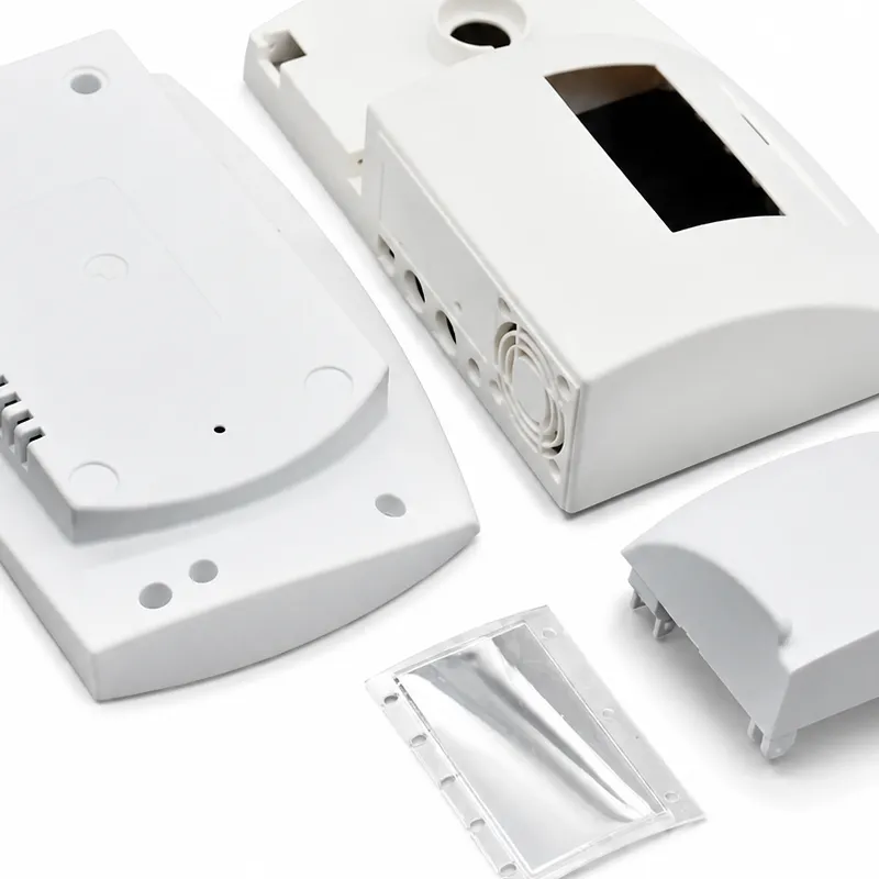
This anonymized case describes the development route for a handheld barcode scanner used in warehouses and service environments. The enclosure had to protect a display, battery, scan engine, trigger, and PCB while remaining comfortable for repeated one-handed use. The primary engineering target was an IP67-style sealed architecture, supported by drop resistance and repeatable assembly. The challenge was not simply molding two plastic shells. Sealing performance depended on the relationship between the housing, elastomer gasket, screw bosses, lens, trigger opening, battery door, and assembly process.
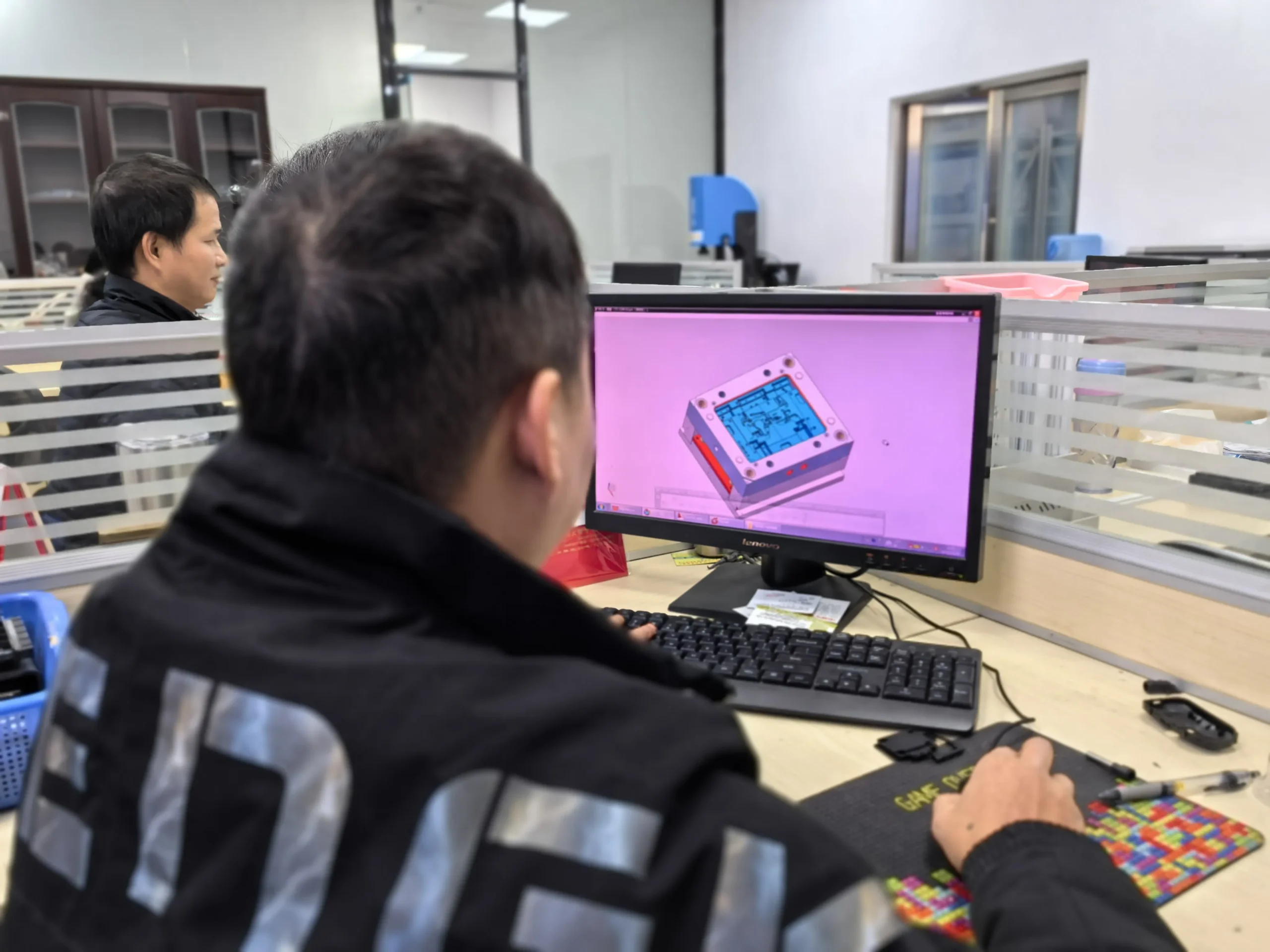
HWPD approached the enclosure as a complete system. The work sequence connected industrial design, mechanical engineering, prototype verification, DFM, mold construction, and process validation. This prevented the common failure in which an attractive exterior is approved before the sealing surfaces and assembly loads are understood.

Why the first enclosure concept carried sealing risk
The initial architecture used a long perimeter gasket compressed between front and rear shells. Several screw bosses were positioned too far from the seal path, allowing the flange to deflect between fasteners. The nominal compression looked acceptable in CAD, but local deformation could reduce contact pressure after a drop or repeated battery replacement. Sharp changes in the gasket path also increased the risk of stretching during assembly.
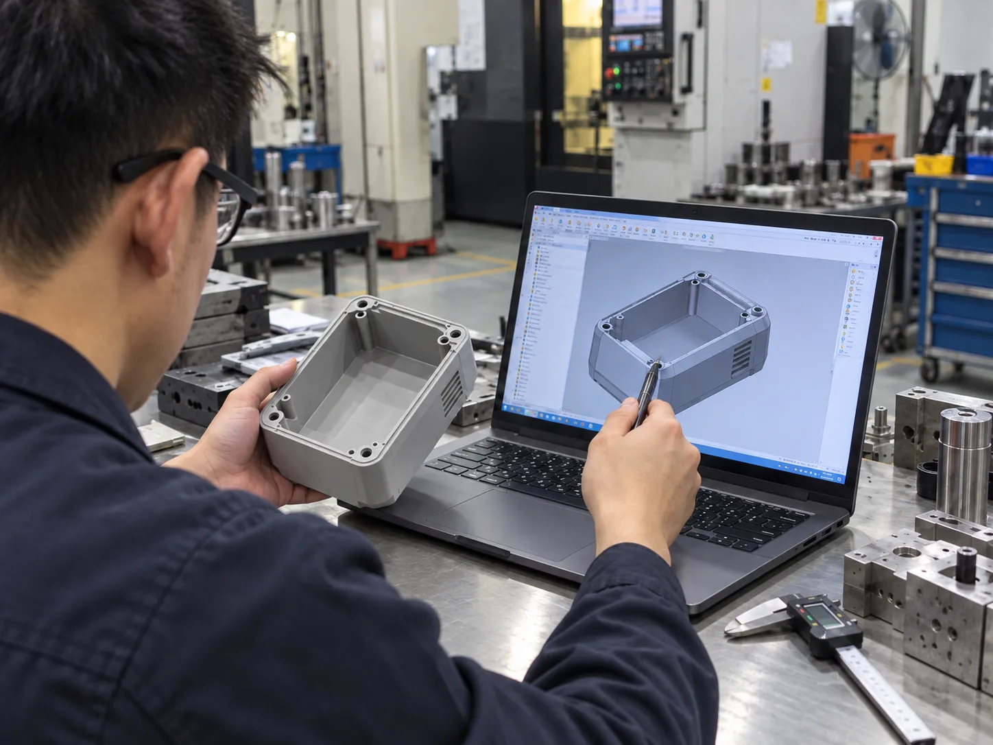
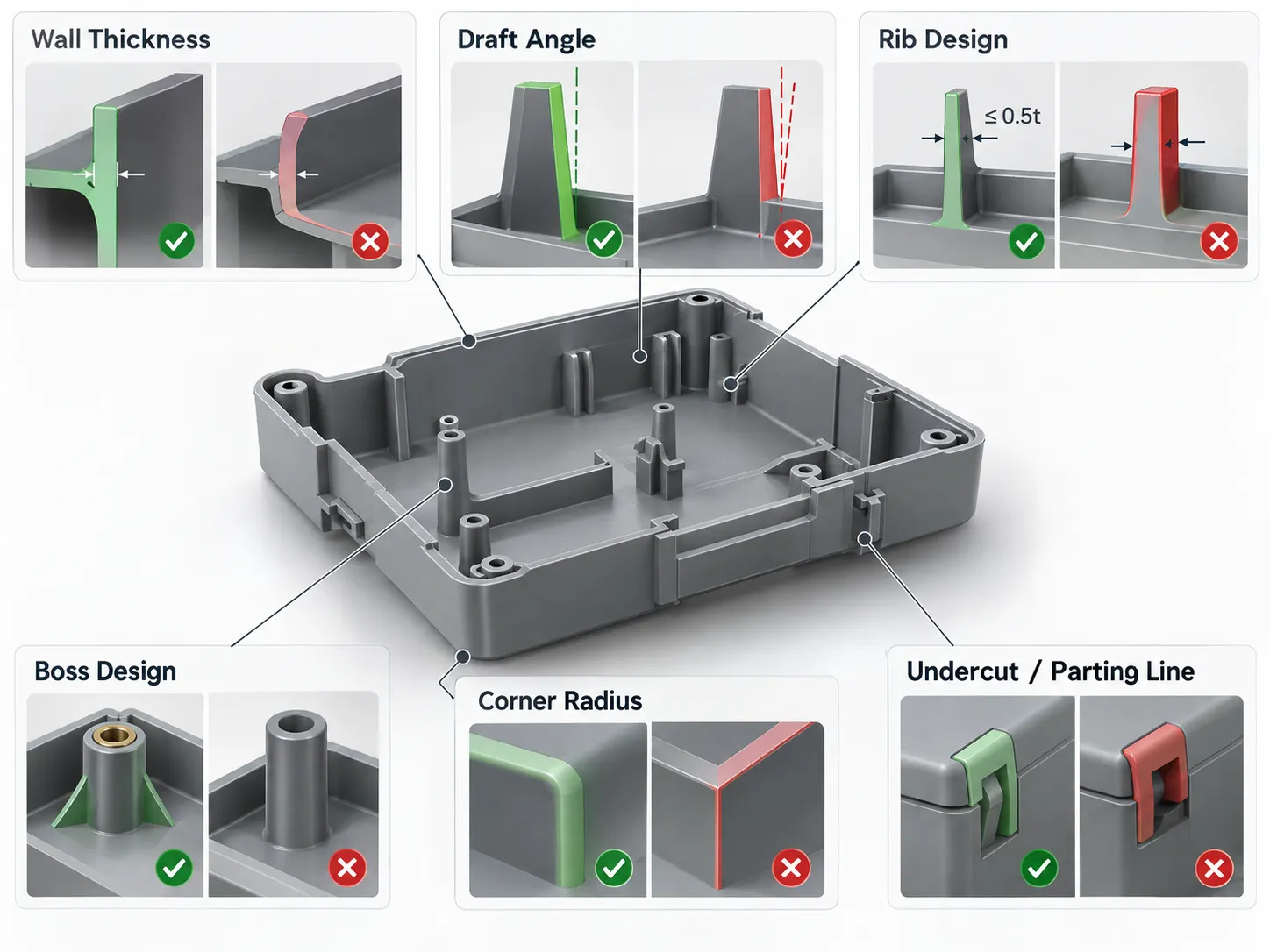
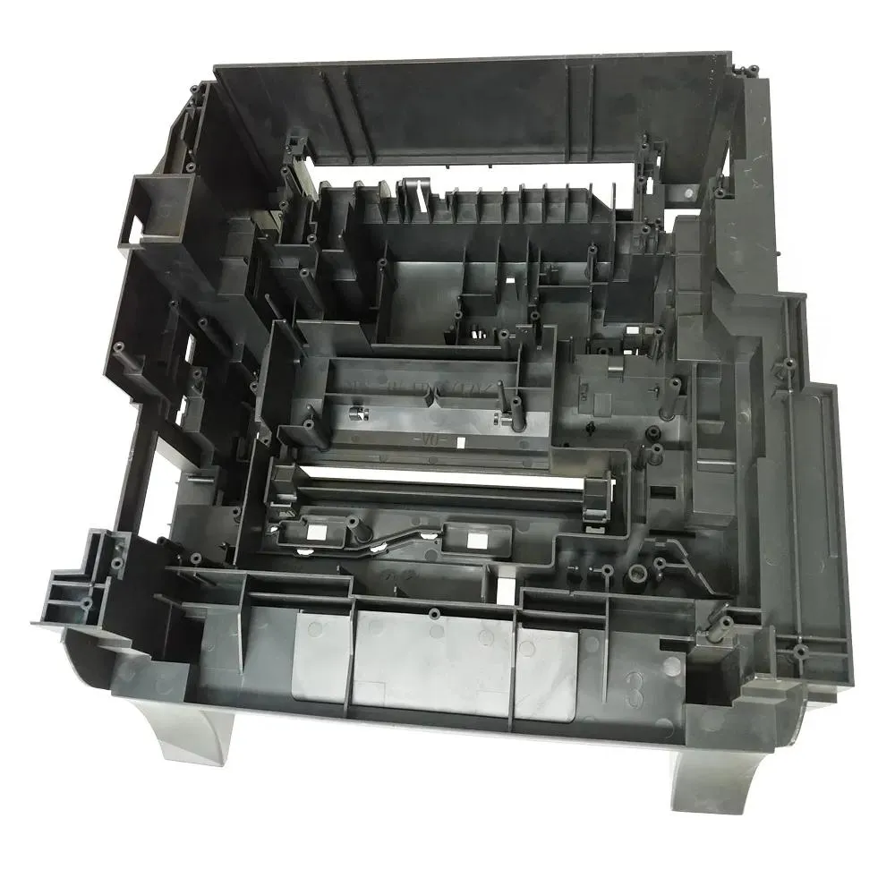
During DFM analysis, the team reviewed wall thickness, draft, shutoffs, boss support, parting-line location, and tolerance accumulation. The gasket channel was simplified, the fastener pattern was balanced around the perimeter, and ribbing was added where it supported clamp load without creating visible sink marks. The lens opening received a controlled bonding land, while the trigger interface was separated from the main environmental seal.
How prototypes were used before tooling
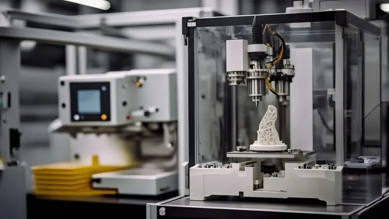
Prototype housings were produced to check hand feel, trigger reach, battery access, PCB clearance, and serviceability. Separate soft parts were used to evaluate gasket installation rather than treating the elastomer as a decorative component. The prototype stage did not attempt to predict every injection-molding detail; its purpose was to expose assembly conflicts and sealing weaknesses while geometry was still inexpensive to change.
The rapid prototyping plan included dimensional inspection at the seal flange and controlled water-ingress checks after assembly. Drop orientation was also considered because a corner impact can momentarily open a poorly supported joint. Findings were recorded against specific CAD revisions so that later changes could be traced.

Tooling and molding decisions
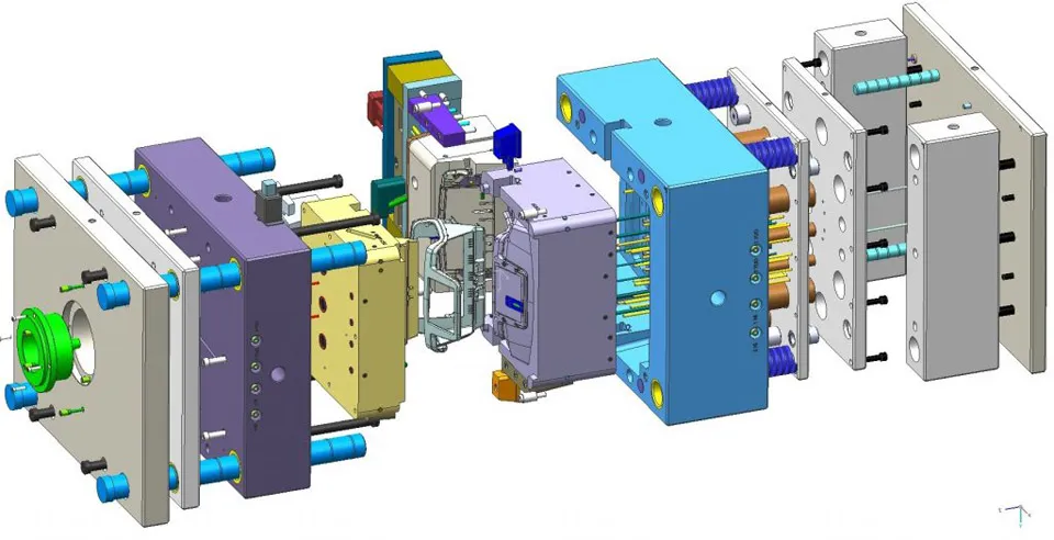
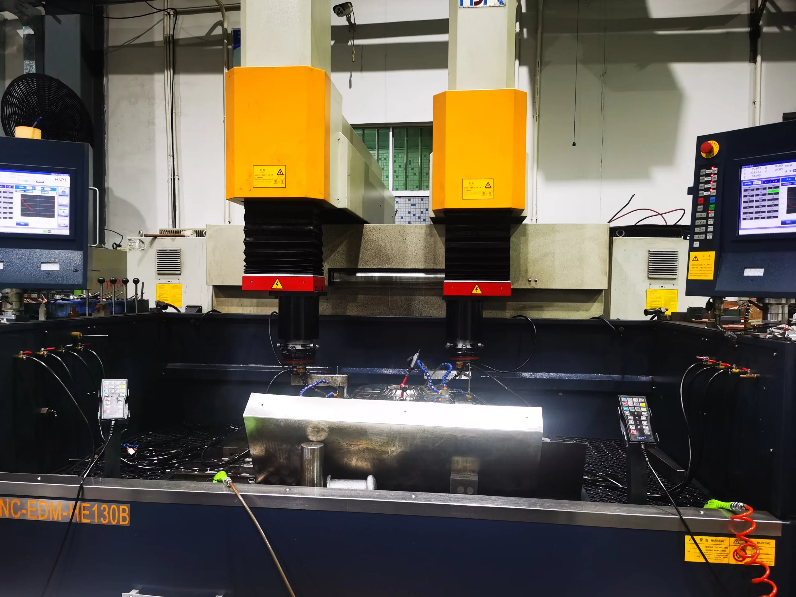
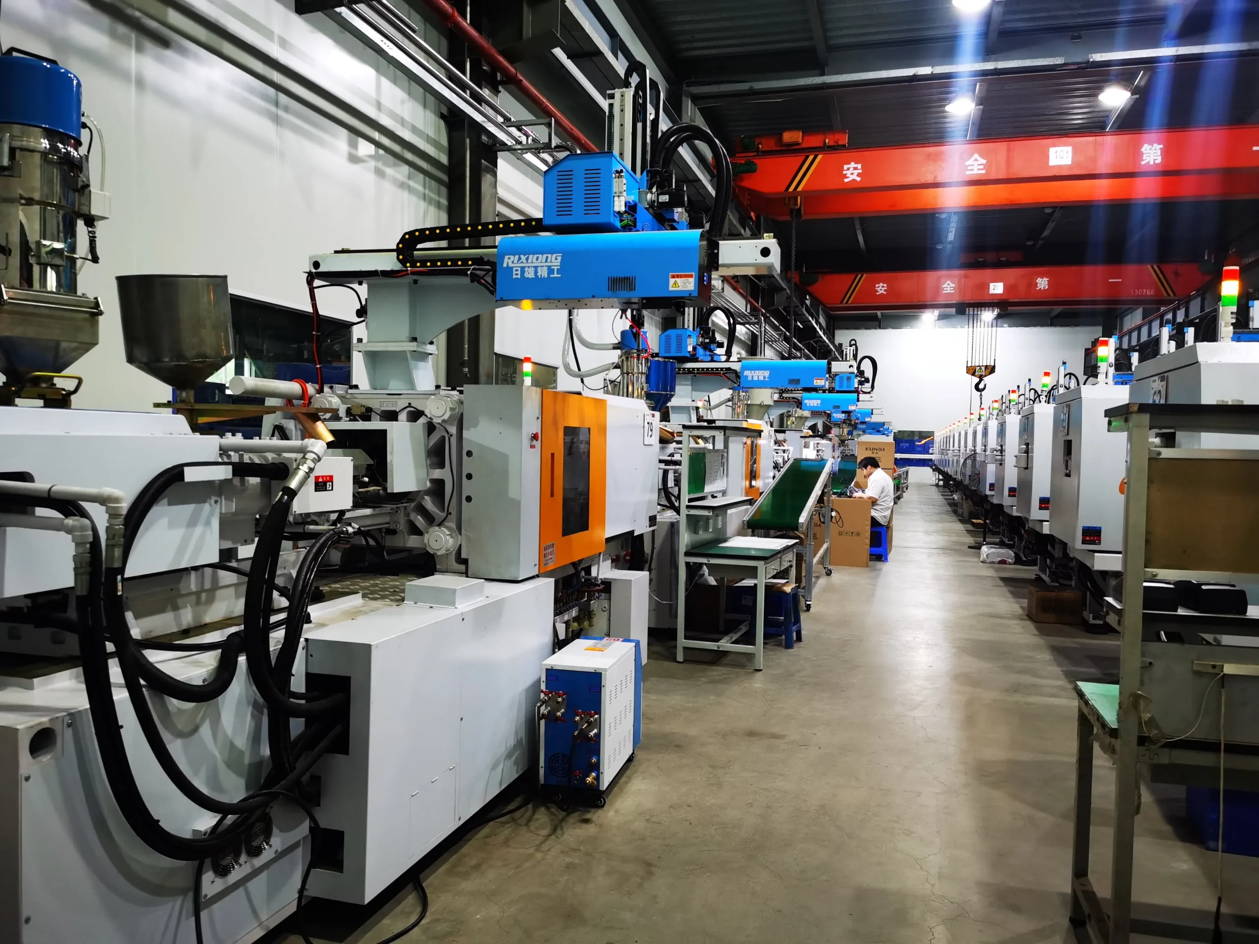
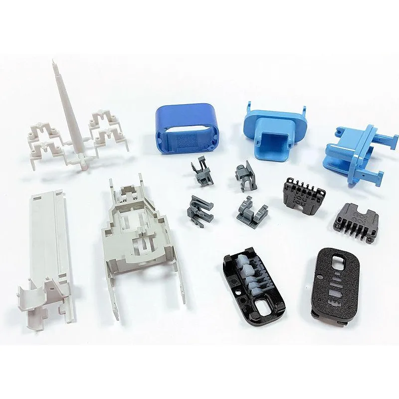
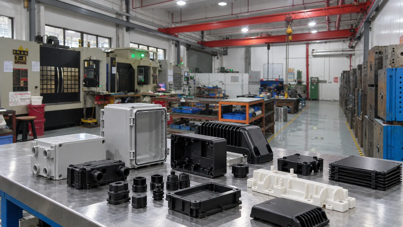
The production design used stable wall transitions, supported screw bosses, and clearly defined cosmetic zones. Gate position was selected to fill the grip and head sections without placing a visible vestige on a contact surface. Venting was concentrated near expected end-of-fill regions, and ejector locations were kept away from sealing lands. The mold design review also considered steel access for future adjustment because seal performance may require small, controlled changes after the first trial.
Material selection balanced impact behavior, dimensional stability, surface quality, and chemical exposure from routine cleaning. The final grade should always be confirmed against the customer’s operating temperature, disinfectant, UV, flame-rating, and regulatory requirements. Processing windows must follow the resin supplier’s data rather than generic temperature settings.
Validation and production control
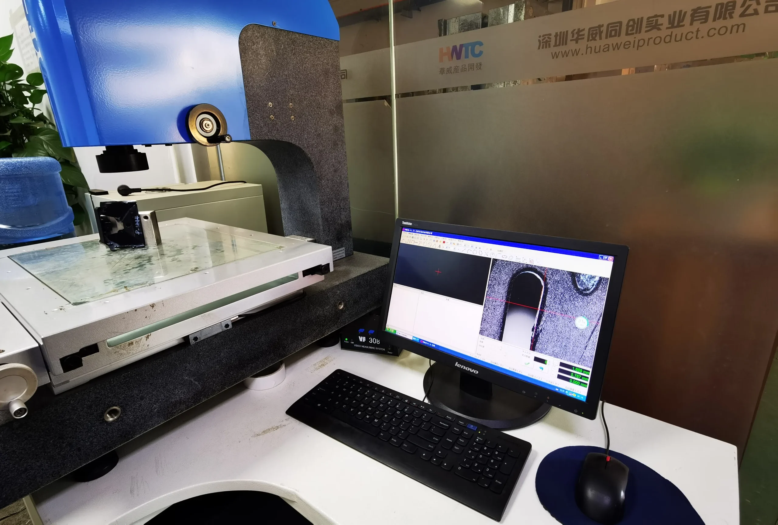
T1 parts were inspected before functional conclusions were made. Critical dimensions included flange flatness, gasket-groove width and depth, boss height, lens land, and battery-door engagement. Assembly torque was controlled because excessive torque can distort a plastic flange while insufficient torque reduces gasket compression. Water-ingress and drop tests were repeated on parts produced within the intended process window, not only on hand-selected samples.
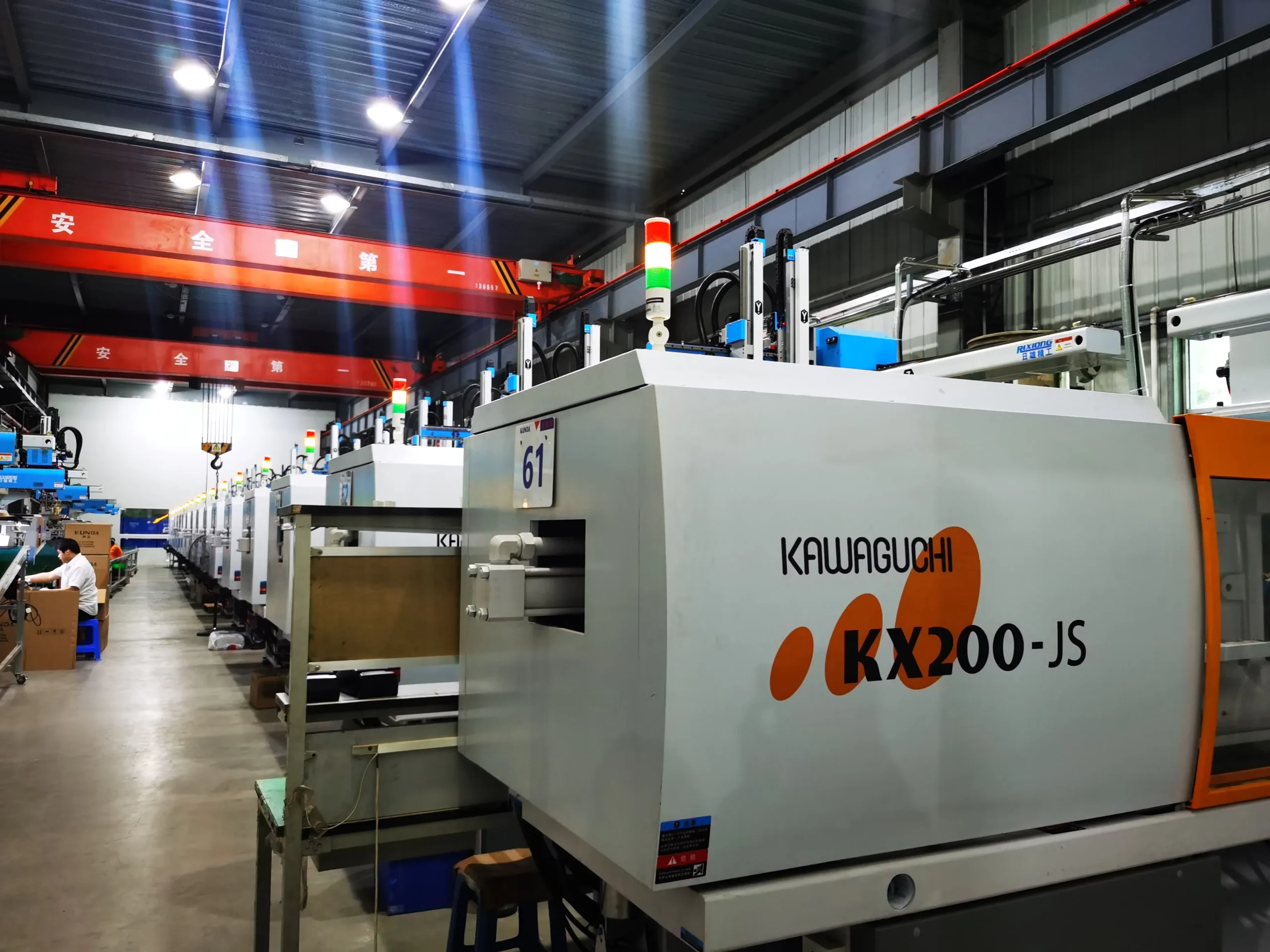
The production control plan linked molding conditions, dimensional checks, assembly torque, gasket inspection, and final functional testing. That connection is what makes a sealed enclosure repeatable. A single successful sample is not evidence of a capable process; the enclosure must remain functional across cavities, lots, operators, and normal process variation.

Change control and service considerations
The released package defined the housing revision, gasket specification, screw and torque requirement, lens-bonding process, resin grade, texture, and inspection datums. Those items were controlled together because changing only one could alter sealing pressure. Service trials also checked that a trained technician could open and reassemble the enclosure without pinching the gasket, cross-threading a screw, or contaminating the lens. Replacement parts had to remain compatible with the same interface definition.
For production handoff, the team retained approved samples, dimensional reports, test fixtures, mold-maintenance points, and a response plan for leakage or drop failures. This evidence made later troubleshooting specific: engineers could compare a suspect unit with the approved assembly and determine whether the difference came from molding, gasket condition, torque, bonding, or handling.
Outcome and engineering lesson
The design reached a production-ready state through coordinated control of geometry, material, tooling, and assembly. The most important lesson was that an IP target cannot be added at the end of development. It must shape the enclosure architecture from the first mechanical layout. For similar products, HWPD can support the path from early design through injection molding and production validation.