






CASE STUDY 02 | CONSUMER ELECTRONICS
A compressed development program linked industrial design, prototyping, DFM, tooling, and injection molding for a crowdfunding launch.
Industry: Consumer Electronics
Project Snapshot
| Project Parameter | Case Value |
|---|---|
| Starting point | Concept sketch |
| Reported development cycle | 14 weeks |
| Launch quantity | 5,000 retail-ready units |
| Design iterations | 3 |
| Core services | Industrial design, DFM, prototyping, tooling, injection molding |
Project Overview
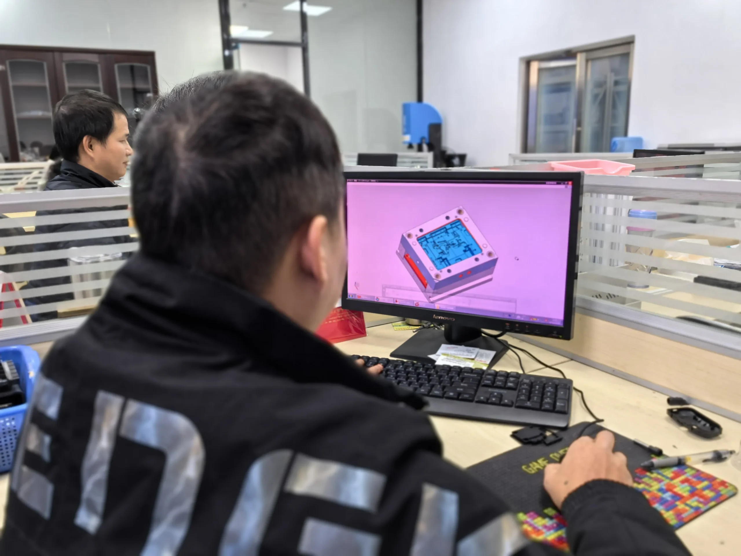
A consumer-electronics startup approached HWPD with a concept sketch for a smart home hub and a launch schedule tied to crowdfunding. According to the current Product Development Cases page, the program moved through three design iterations and delivered 5,000 retail-ready units in 14 weeks. HWPD supported industrial design, DFM analysis, rapid prototyping, tooling, and injection molding rather than dividing the project among unrelated suppliers.
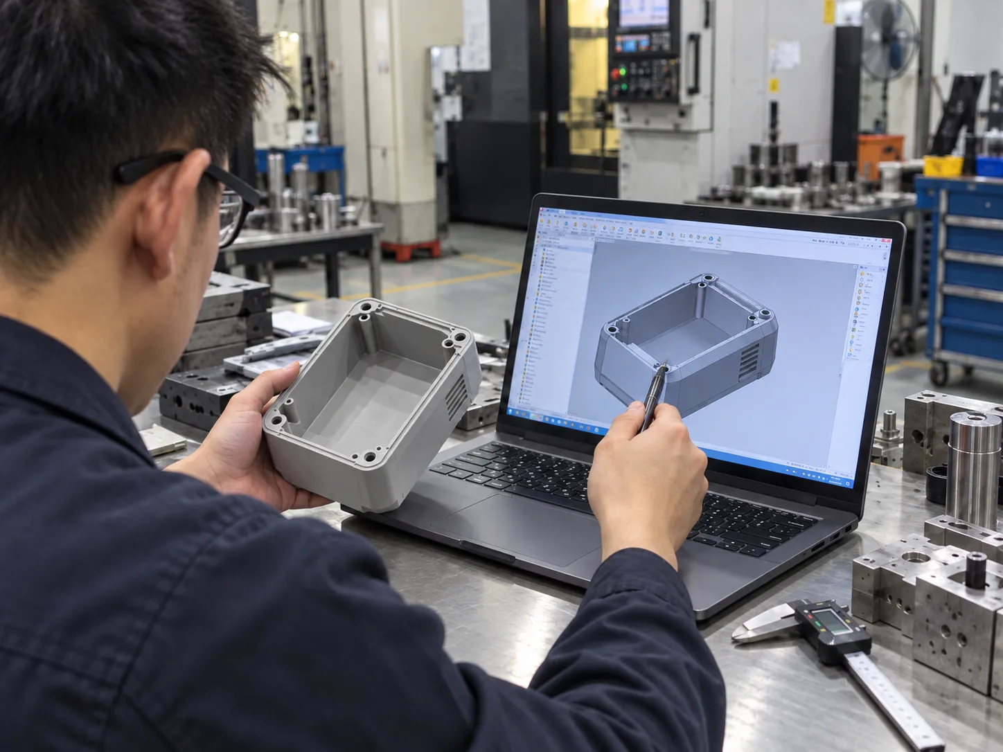
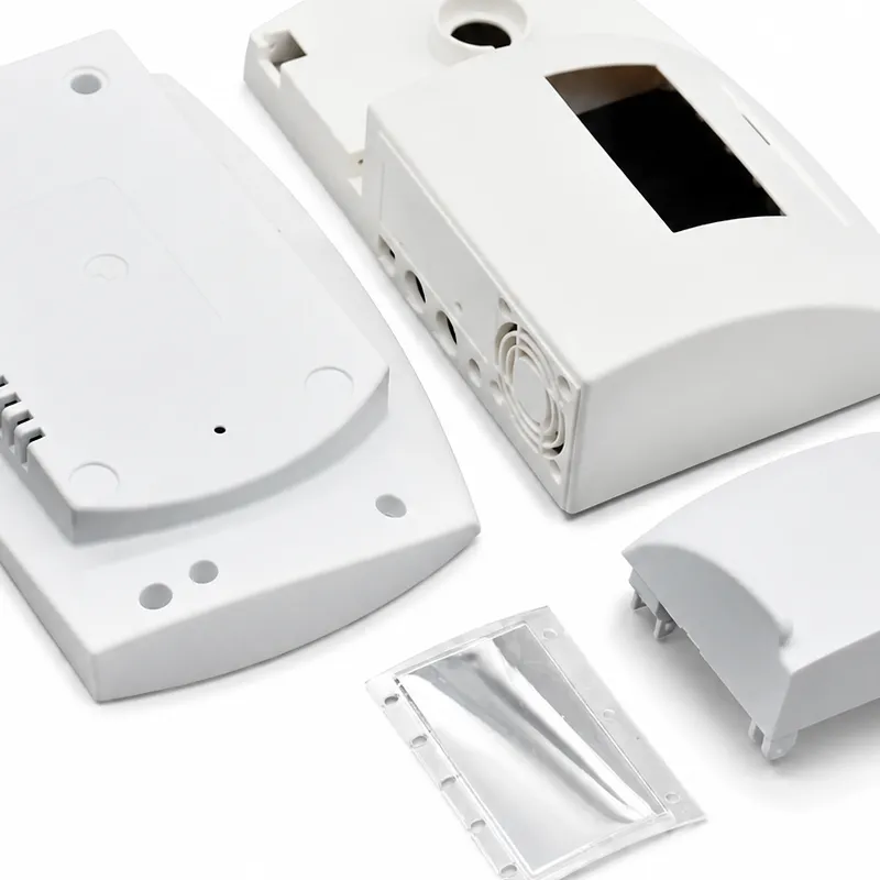
That integrated route is particularly valuable for connected hardware. A smart home enclosure has to look intentional on a desk or wall, but it also has to package electronics, connectors, vents, LEDs, fasteners, and assembly features. The end-to-end product development workflow allows those industrial-design and manufacturing decisions to evolve together instead of waiting for a late handoff.
The Schedule Challenge
A 14-week concept-to-retail window leaves little room for sequential work. If industrial design is fully finished before engineering begins, or if tooling starts before the assembly has been physically checked, delays accumulate quickly. The safer strategy is controlled overlap: aesthetic decisions, mechanical packaging, prototype testing, and manufacturability review advance in parallel with clear design-freeze gates.
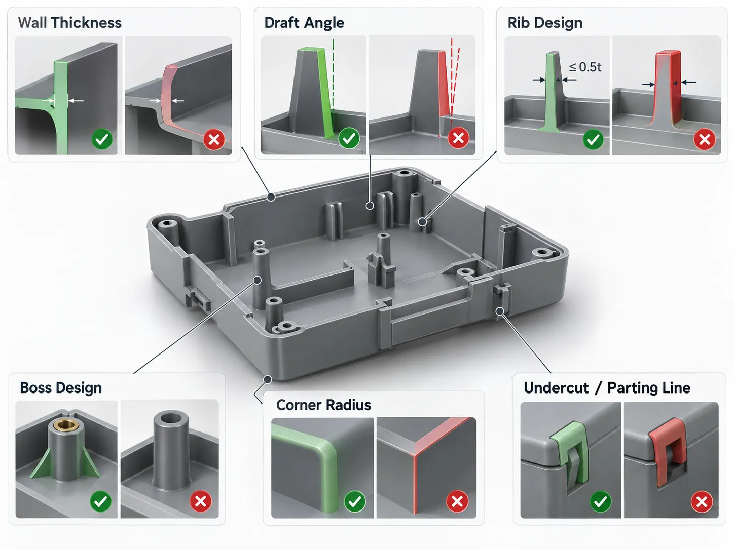
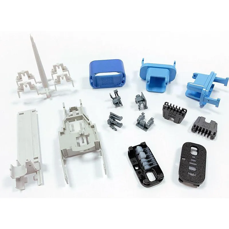
The three reported design iterations are significant because iteration is not wasted time when it eliminates tooling risk. Early industrial design can establish proportion, user interaction, surface breaks, and visual hierarchy, while engineering converts those choices into producible wall sections, draft, ribs, bosses, snap features, and assembly interfaces.
Prototype Before Tooling
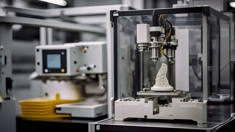
For a smart home product, prototypes can answer different questions at different stages. An appearance model can confirm size and visual balance; a functional prototype can verify PCB packaging, connector access, cable routing, ventilation, indicator visibility, and screw locations. Rapid prototyping is most useful when the team defines what each iteration must prove instead of simply printing the latest CAD file.
Before tool release, the prototype assembly should expose tolerance and service issues that are difficult to see on screen. Panel gaps, clip engagement, connector clearance, button travel, lens position, and assembly sequence can all be checked while geometry changes remain inexpensive. This is how rapid iteration protects the launch schedule rather than competing with it.
DFM, Tooling, and Launch Production
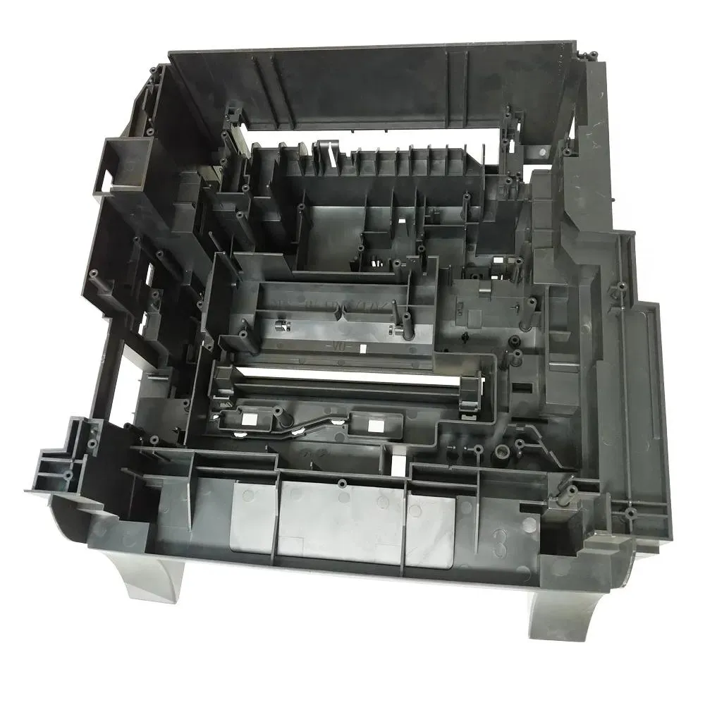
Once the design stabilized, DFM analysis connected the enclosure to injection molding. The review should confirm wall consistency, draft, undercuts, cosmetic surfaces, gate-sensitive areas, ejection, ribs, screw bosses, and the location of weld lines or witness marks. In a consumer product, hidden manufacturing features must be planned around the surfaces the customer actually sees.
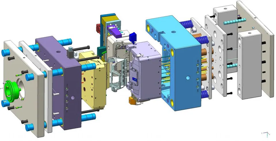
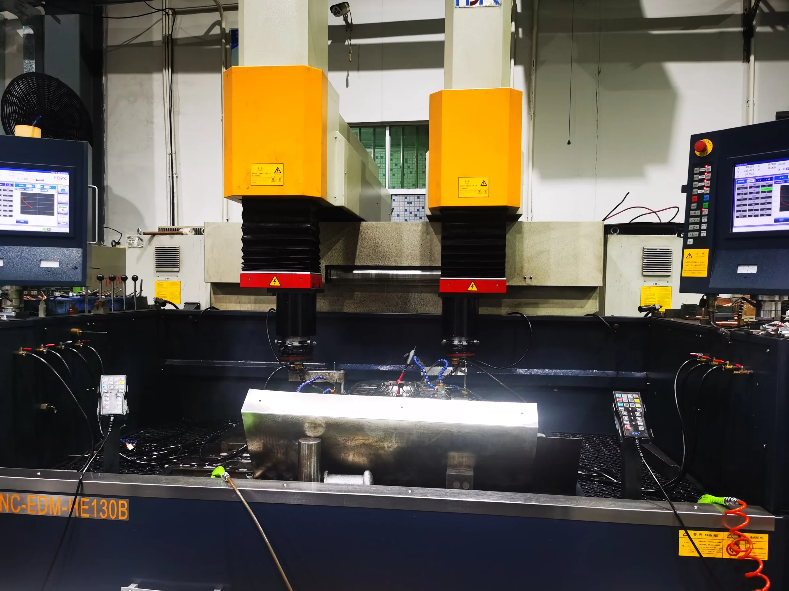
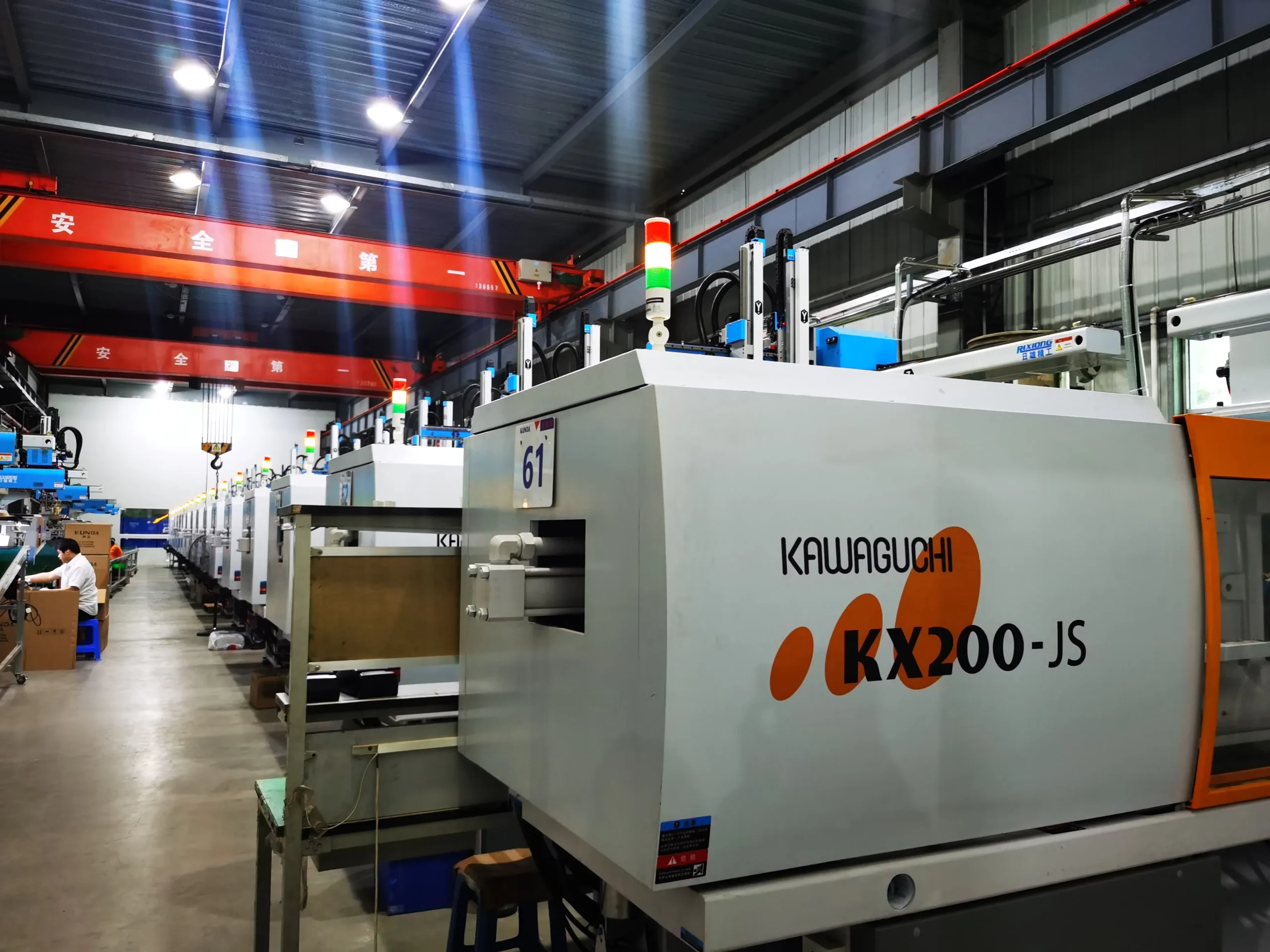
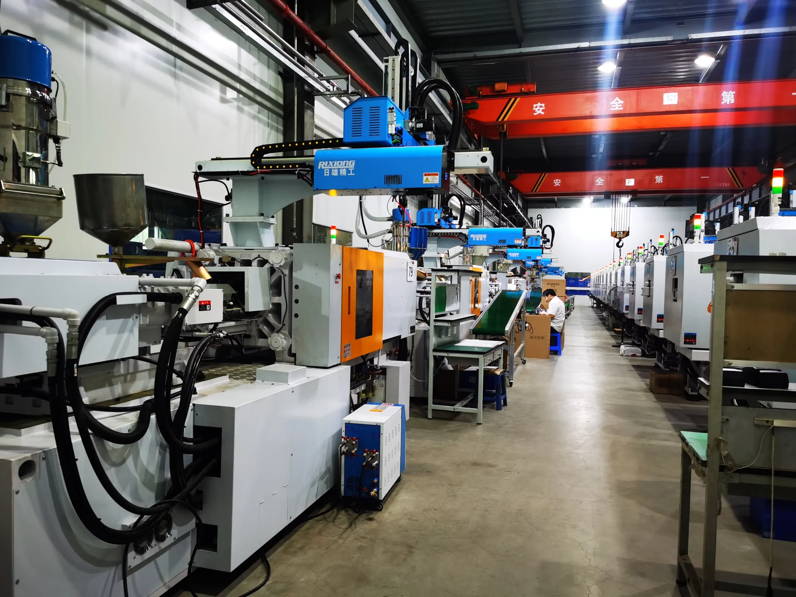
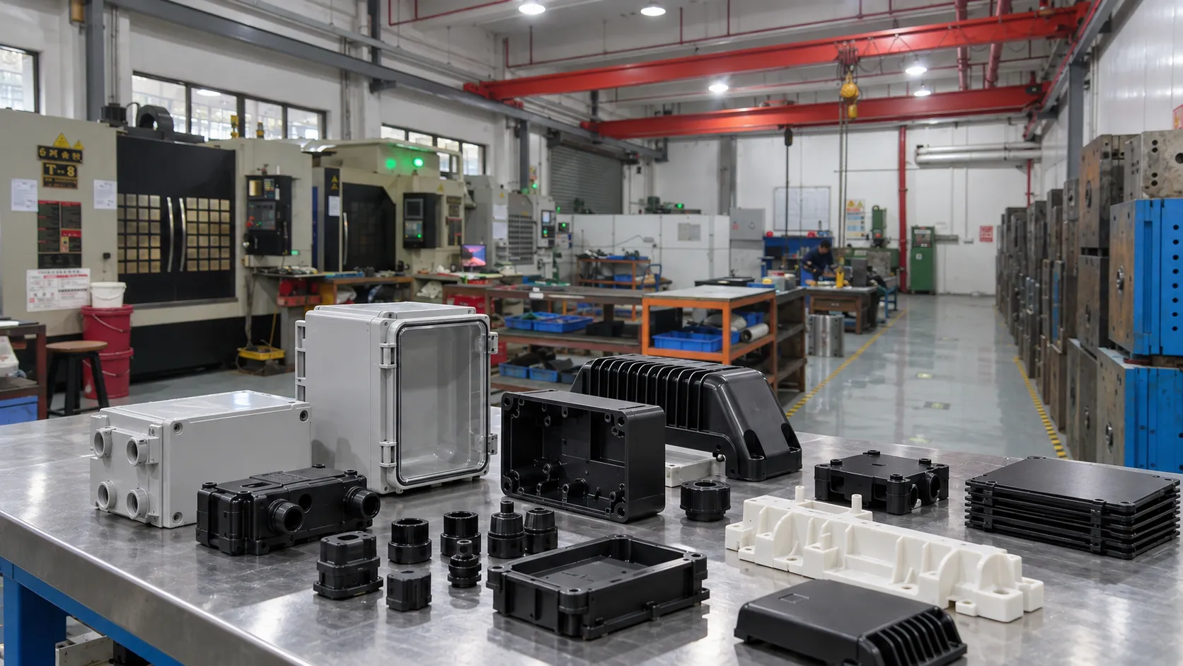
The mold then becomes the bridge between approved design intent and the 5,000-unit launch quantity. Mold manufacturing and sampling need to preserve not only geometry but also the appearance standard established during design. Color, texture, gloss, parting-line condition, fit between shells, and assembly behavior all become production criteria before retail units are packed.
Results and What the Case Shows
The published case records a 14-week sketch-to-retail schedule, 5,000 launch units, and three design iterations. Those numbers show why startups benefit from a staged program rather than jumping from a sketch directly to hardened production tooling. The project used iteration to reduce uncertainty, then converted the approved product into tooling and molded inventory for the launch.
For founders and hardware teams, the key lesson is to manage the schedule by decision gates. Freeze the external architecture only after the product is coherent; freeze tooling geometry only after the prototype assembly answers the important fit and function questions; and release launch production only after molded samples meet the defined cosmetic and assembly standards. Speed comes from removing rework, not from skipping validation.
Practical Takeaways for Similar Programs
A startup following a similar launch path should decide early which requirements are flexible and which are not. External dimensions, PCB keep-out zones, connector locations, antenna clearances, thermal openings, button travel, light-pipe position, and visible surface standards should be ranked before the first prototype. That ranking lets the team change low-risk geometry quickly while protecting the interfaces that would trigger expensive redesign downstream.
The launch quantity should also be treated as an engineering input. Five thousand units require more discipline than a handful of samples: repeatable color, stable panel gaps, defined assembly work instructions, incoming component checks, packaging protection, and a method for handling nonconforming parts. A fast consumer-electronics launch succeeds when product design and manufacturing readiness reach the finish line together, not when the enclosure mold happens to be completed first. Teams should also reserve time for pilot assembly, packaging checks, and a short controlled production run before the full crowdfunding quantity is released.
Conclusion
This smart home program demonstrates how product development, prototyping, tooling, and injection molding can operate as one launch system. Starting with a concept sketch, the team completed three iterations and reached 5,000 retail-ready units within the 14-week timeline reported by HWPD. The same framework applies to many connected products: develop appearance and packaging together, prototype the interfaces that matter, use DFM before tool release, and keep design, tooling, molding, and assembly decisions under one coordinated project plan.