






An injection mold is not simply a block of steel with a cavity cut into it. It is a production system that must repeatedly control molten plastic, pressure, cooling, ejection, alignment, venting, and dimensional accuracy over thousands or millions of cycles. A reliable mold manufacturing program therefore starts long before machining. It begins with an approved part design, a clear production target, and a tooling strategy that connects expected volume, resin, tolerance, appearance, cycle time, and maintenance requirements.
1. DFM Starts the Injection Mold Manufacturing Process
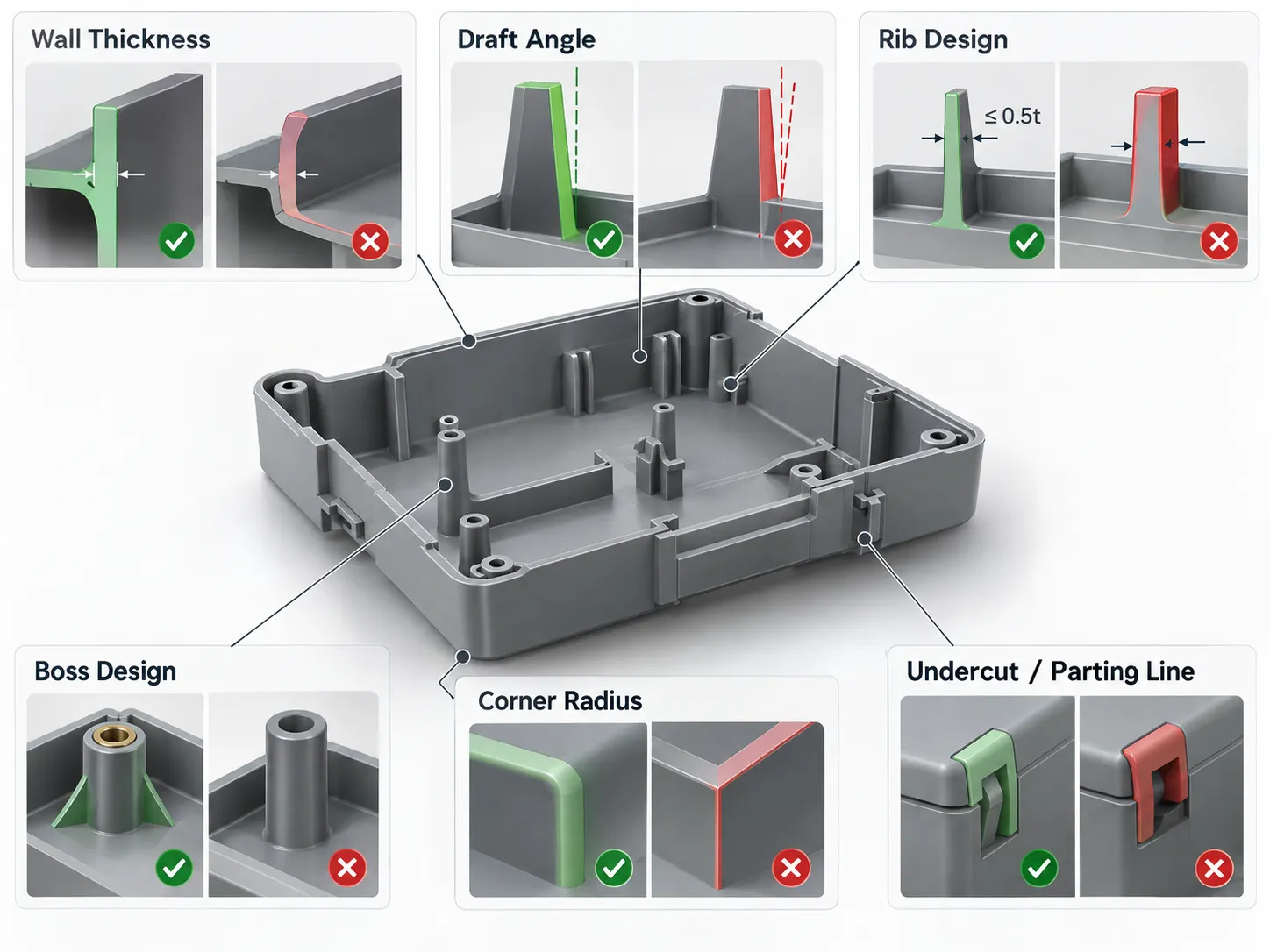
Before steel is ordered, the part should pass a structured DFM analysis. Engineers review wall thickness, draft, ribs, bosses, undercuts, shutoffs, parting lines, gate options, ejection zones, cosmetic surfaces, and expected shrinkage. This step is important because a small CAD change can eliminate a slider, improve venting, move a gate away from a visible surface, or reduce a thick section that would otherwise create sink. DFM is also the stage to identify critical-to-quality dimensions and decide which areas may need steel-safe conditions for later tuning.

2. Mold Design Converts the Part Into a Production System
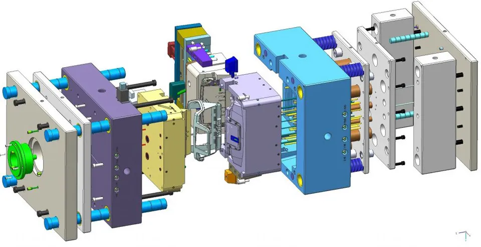
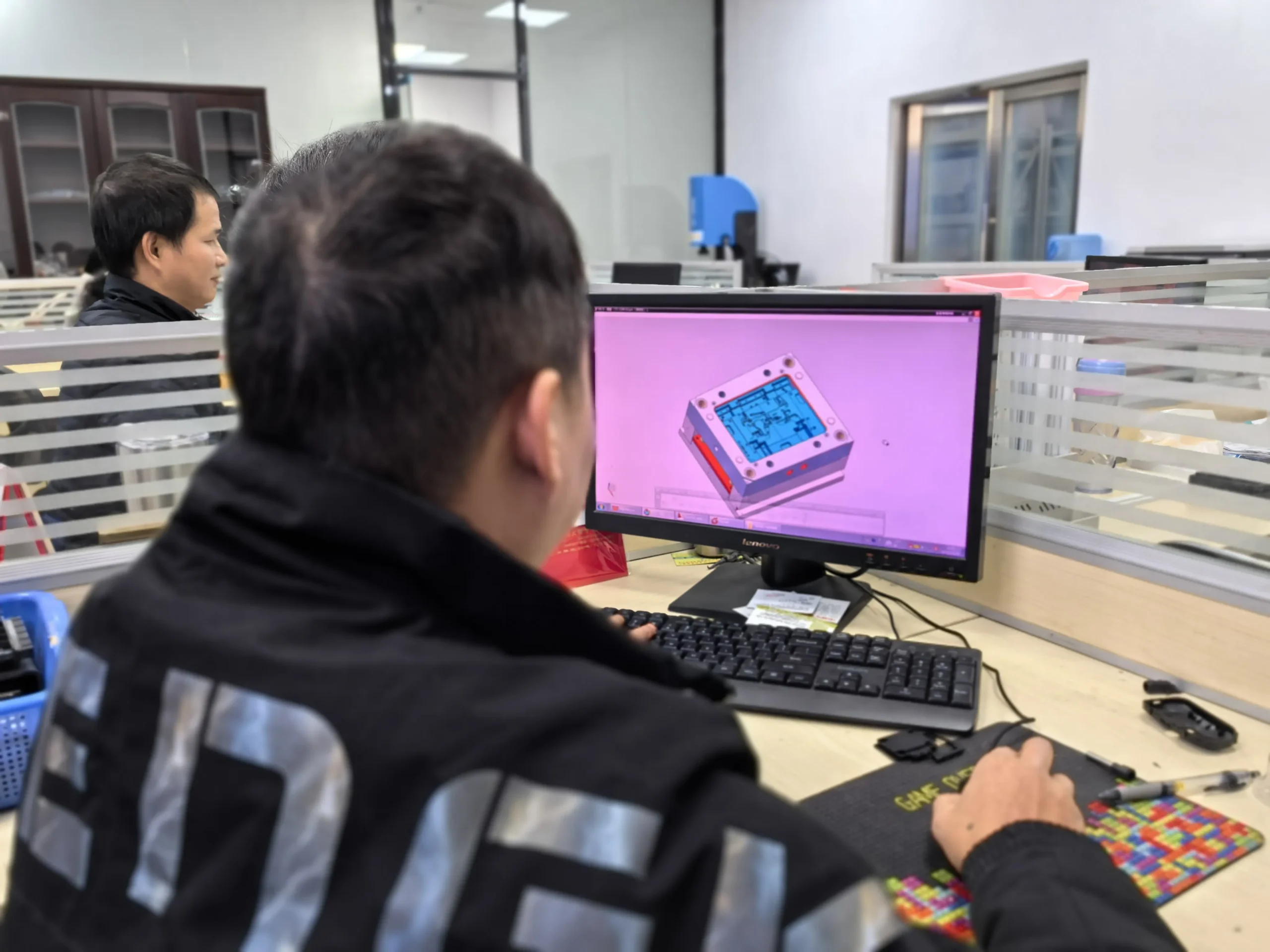
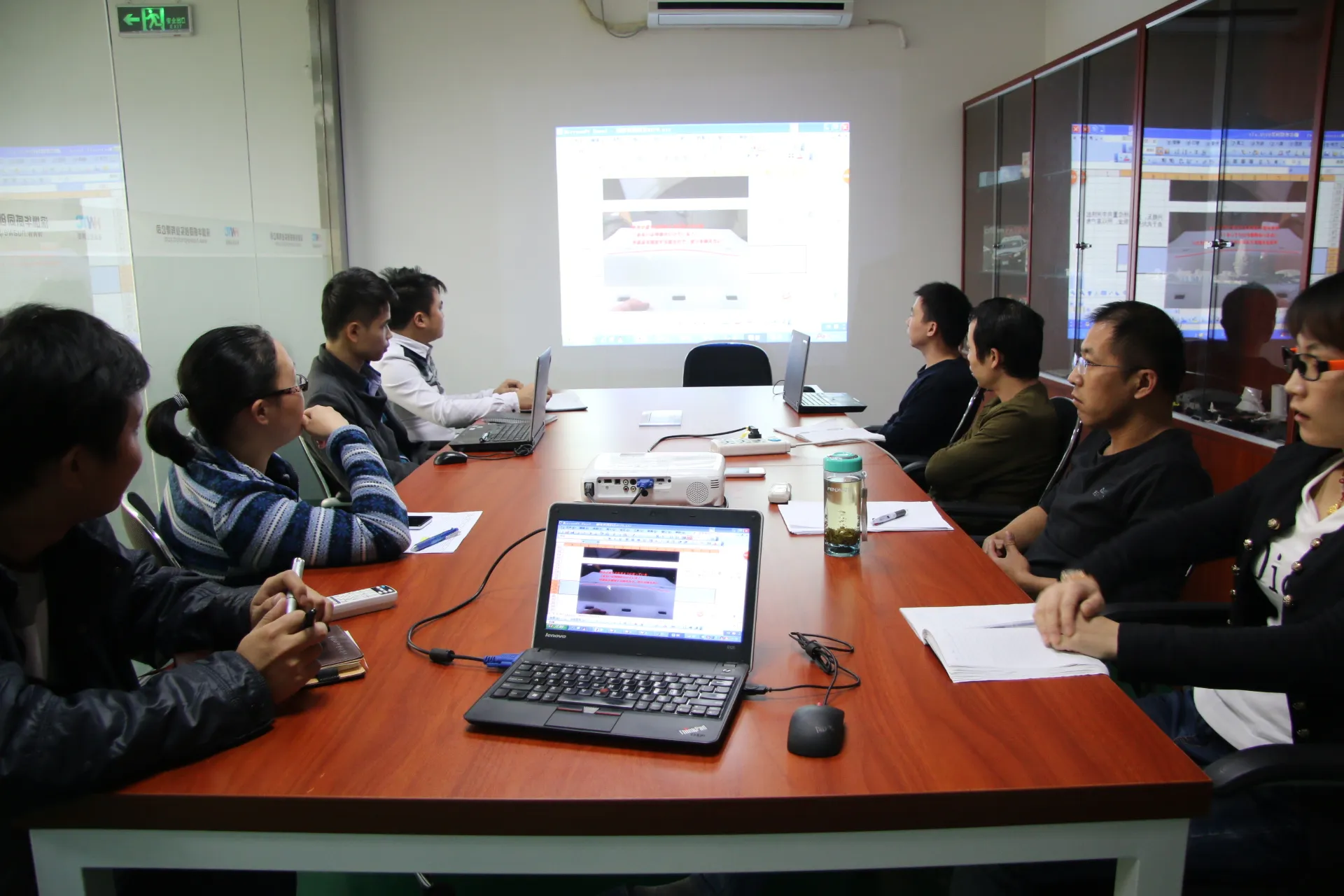
Once the part geometry is approved, mold design turns that geometry into cores, cavities, inserts, slides, lifters, ejectors, cooling circuits, runner systems, and a mold base. Designers consider how the part fills and releases, where steel must be supported, how maintenance will be performed, and how the tool will interface with the target injection molding machine. For multi-cavity tools, balance becomes especially important because each cavity should fill and cool consistently. The design review should be completed before machining begins, not while components are already on the machine.
3. Tool Steel Is Selected for the Actual Production Requirement
The best steel is not automatically the hardest or most expensive grade. Prototype and bridge tools may use aluminum or pre-hardened P20 when speed and moderate shot life matter most. Higher-volume or abrasive-material programs may justify H13, S136, or other hardened grades. Resin additives, glass fiber, corrosion risk, surface polish, annual volume, expected mold life, and maintenance conditions all affect the decision. Incoming steel should be verified against the approved specification before machining so hardness and grade are known rather than assumed.

4. CNC Machining Creates the Main Mold Geometry
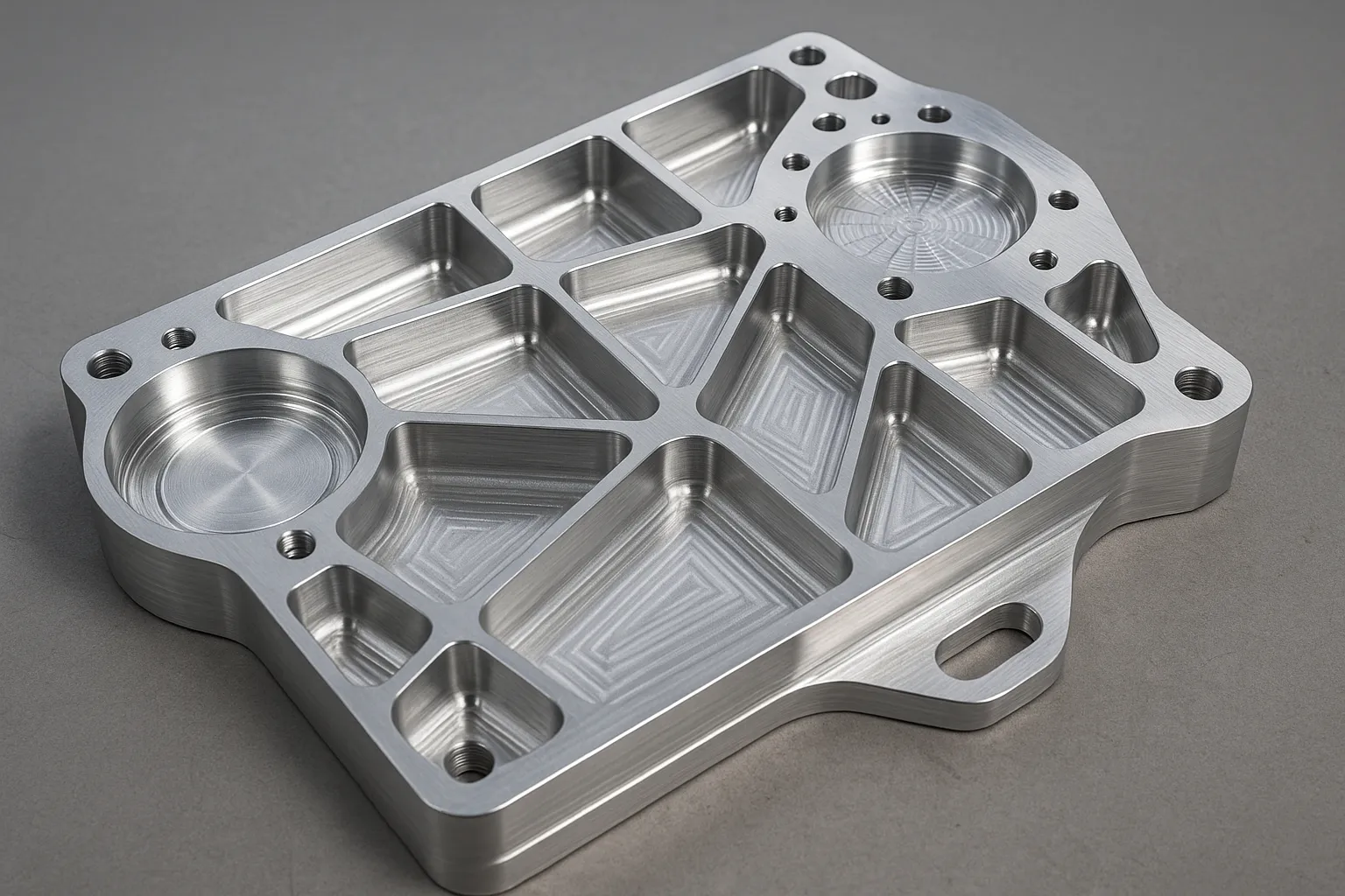
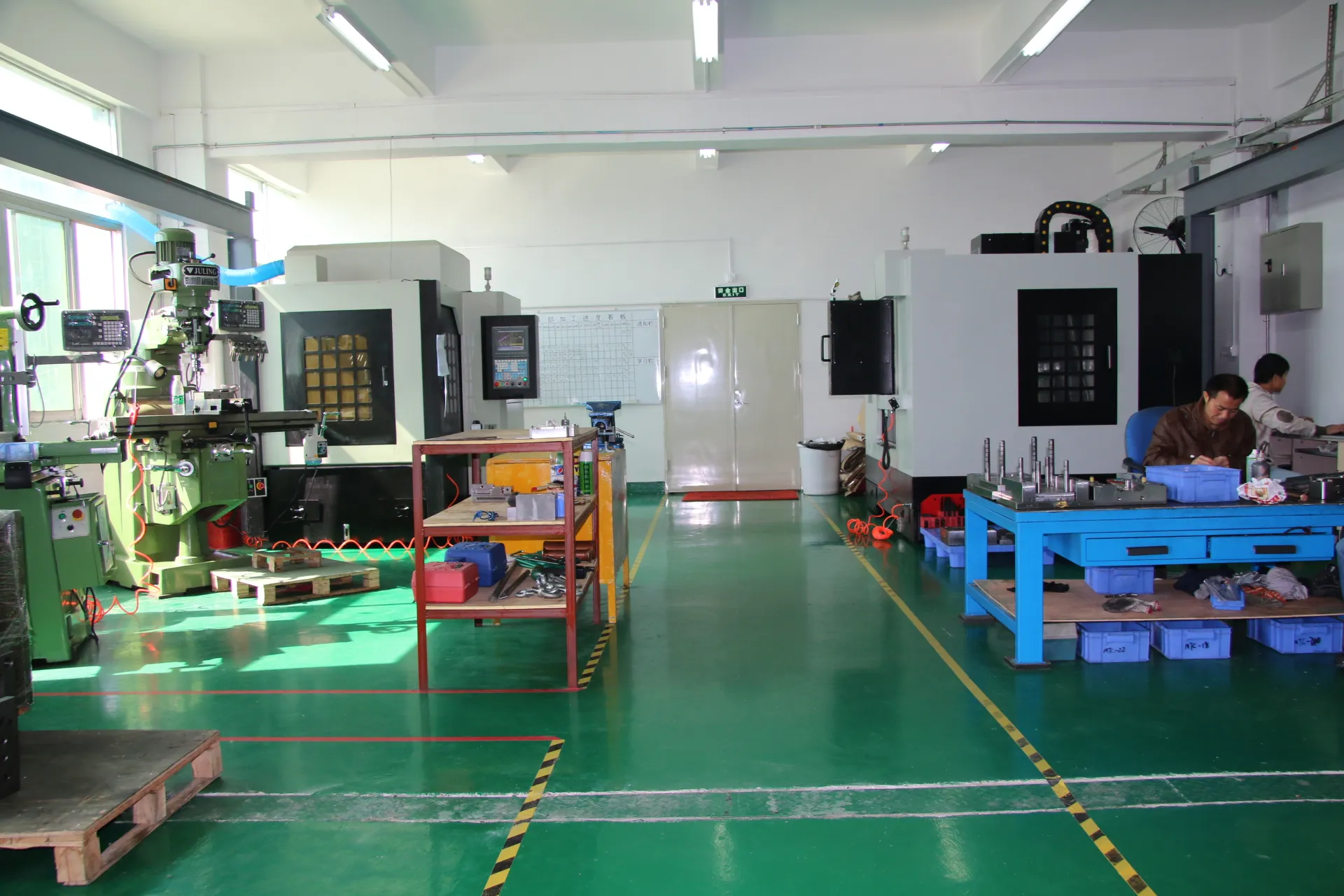
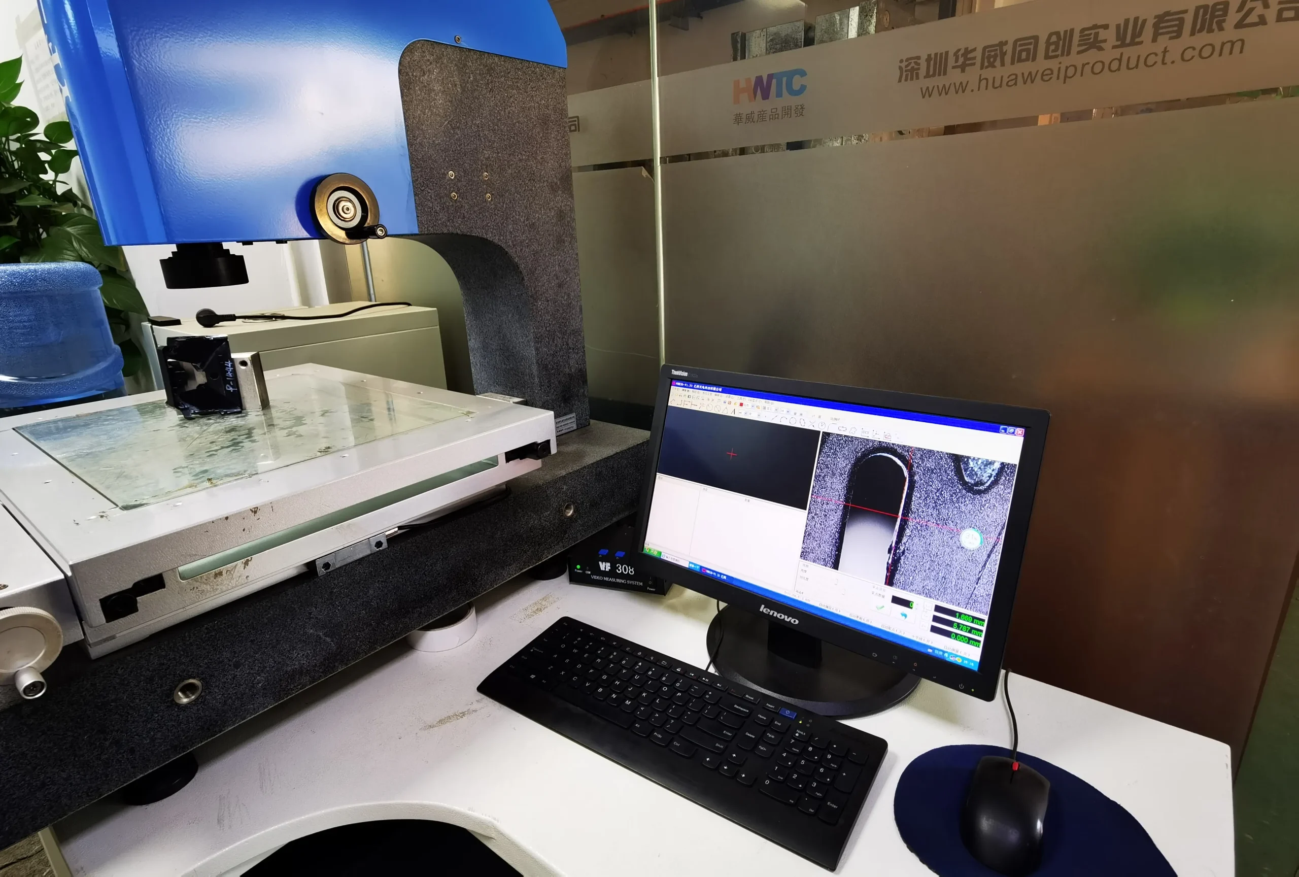
Rough machining removes large amounts of material and establishes the basic core, cavity, and insert geometry. Semi-finish and finish operations then approach final dimensions with smaller tools and controlled cutting strategies. Modern 3-axis and 5-axis machining can produce complex freeform surfaces, cooling features, and electrode geometry with high repeatability. However, mold machining is not just about reaching a nominal dimension. Toolmakers also control reference datums, insert fit, stock allowance for polishing, and relationships between components that must align when the mold closes.
5. EDM Reaches Features Cutting Tools Cannot
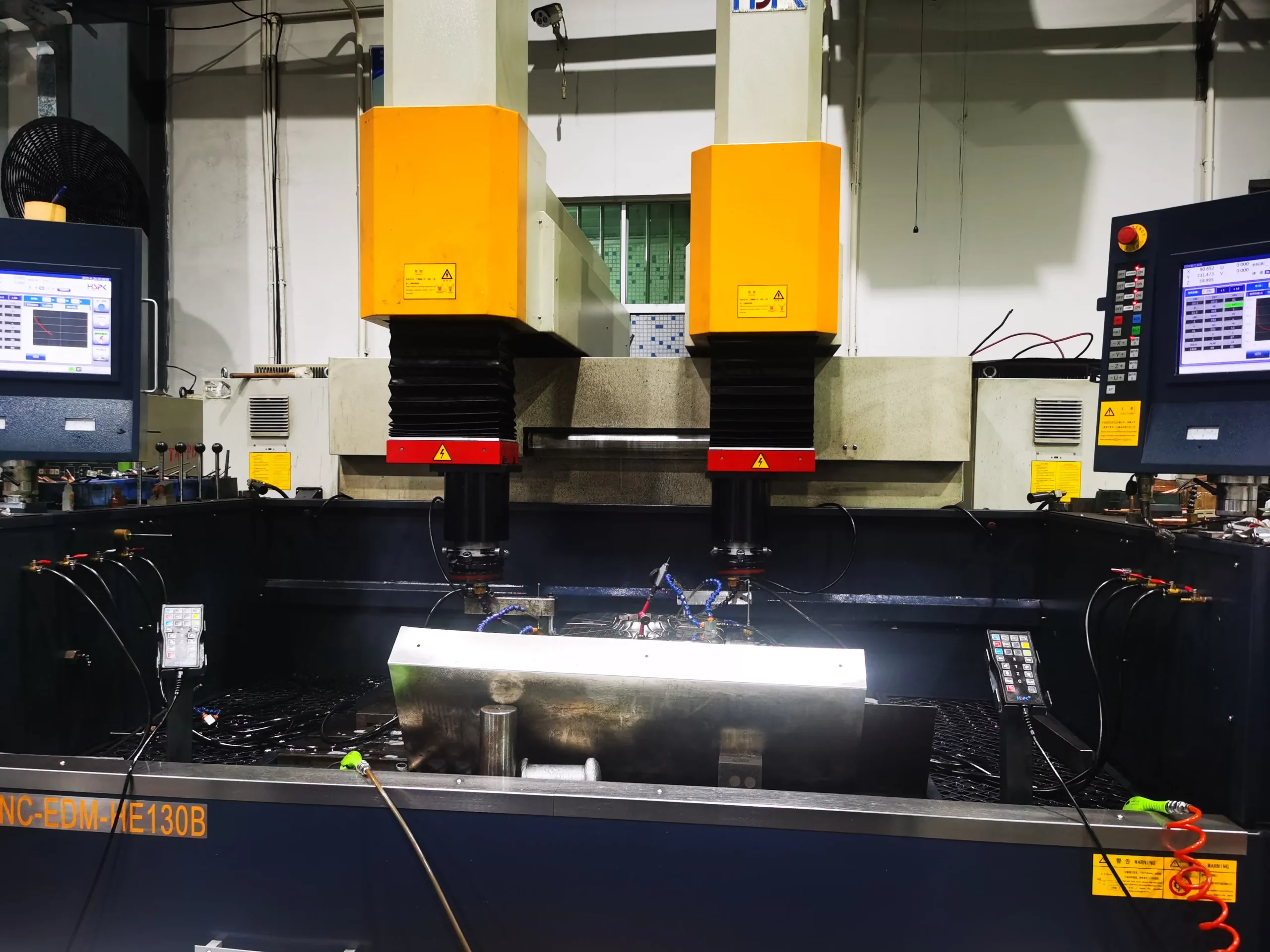
Deep ribs, narrow slots, sharp internal details, and some complex shutoff areas are difficult or impossible to produce with conventional milling cutters. Sinker EDM uses a shaped electrode to erode these features into hardened steel, while wire EDM is commonly used for precise profiles, inserts, and through-features. Electrode design is therefore part of the mold manufacturing plan. Good electrode management reduces unnecessary burns and helps control dimensional accuracy on features that will influence fit, flash, or cosmetic quality.

6. Fitting, Polishing, and Assembly Turn Components Into a Tool
After machining, individual components must work together as a system. Toolmakers fit inserts, slides, lifters, ejectors, wear plates, guide components, and shutoffs. Cosmetic cavities may be polished to a specified SPI finish or prepared for texturing. Cooling lines and water circuits are checked, moving components are tested, and contact areas are spotted to confirm proper closure. This fitting stage is where practical toolmaking experience matters: components can be dimensionally correct on paper yet still require controlled adjustment to move smoothly under real production conditions.
7. Mold Trial Produces the First Real Process Data
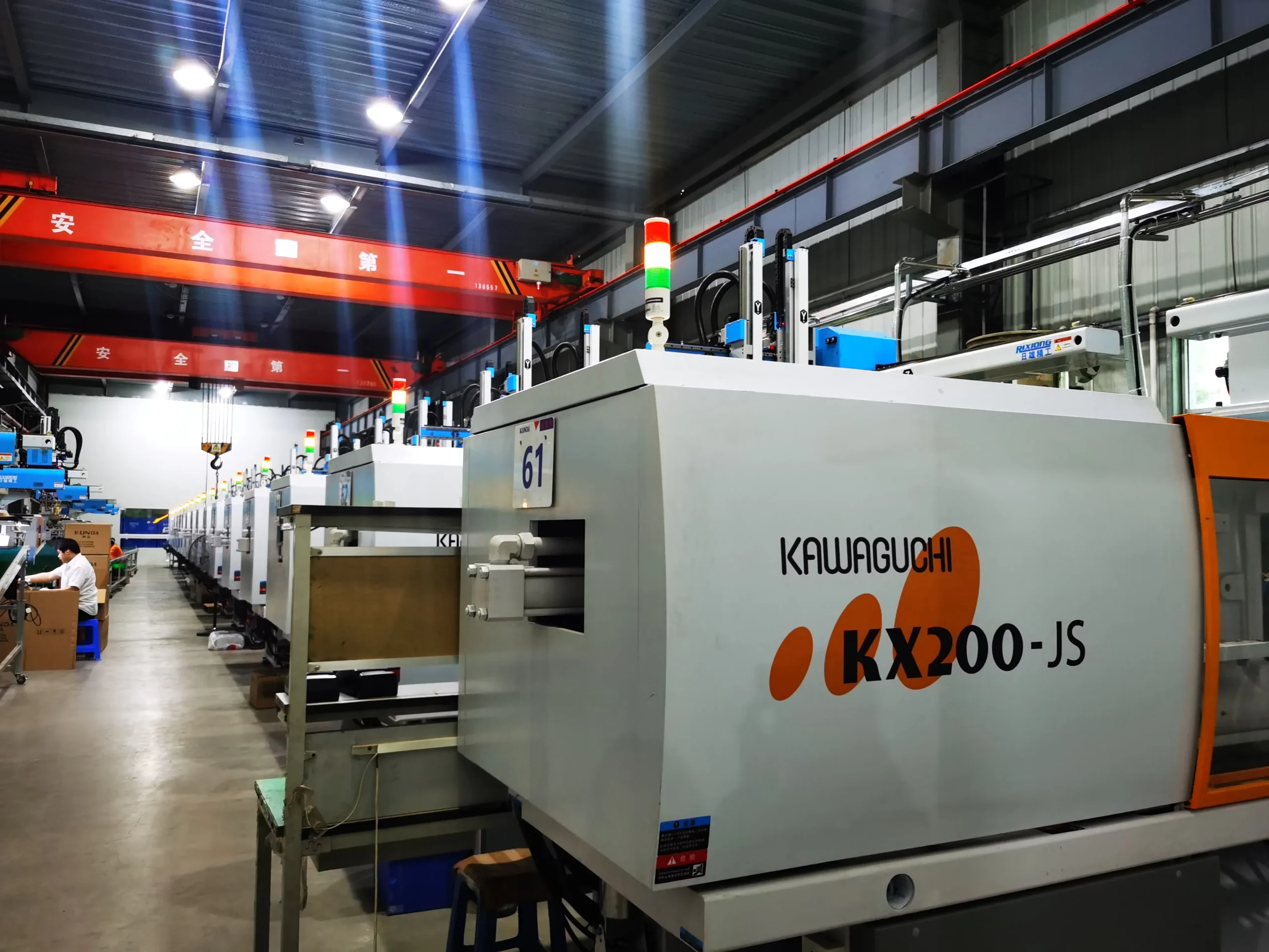
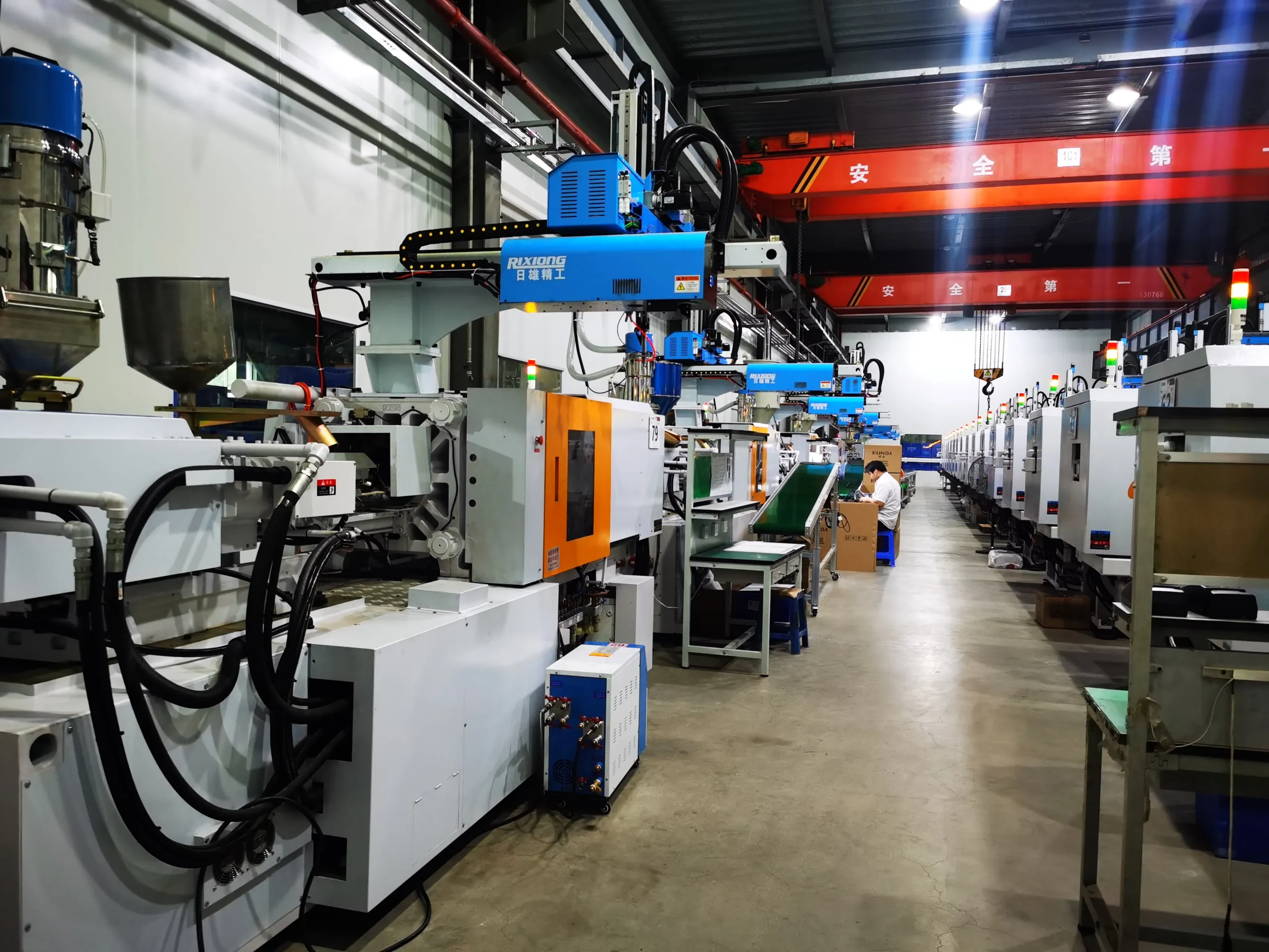
The completed tool is installed in an injection molding machine for the first trial. The objective is not only to make a visually acceptable part. Engineers establish initial melt temperature, mold temperature, fill speed, pressure, hold time, cooling time, and ejection settings while observing fill behavior, flash, short shots, weld lines, sink, warpage, and surface quality. T0 or early trial parts may lead to process adjustments or controlled steel changes. Once the tool reaches the agreed condition, T1 samples can be submitted for customer evaluation.