




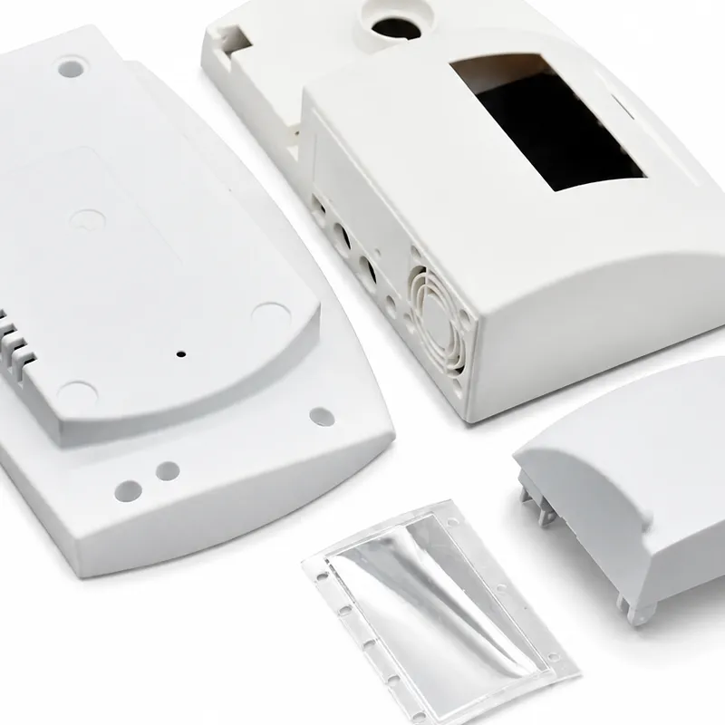
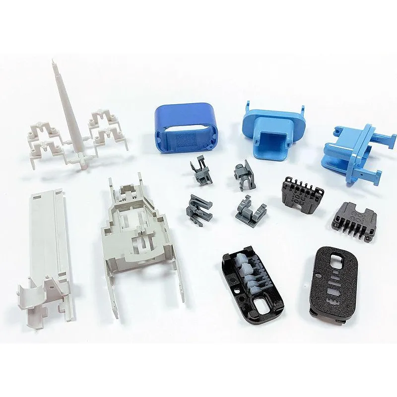
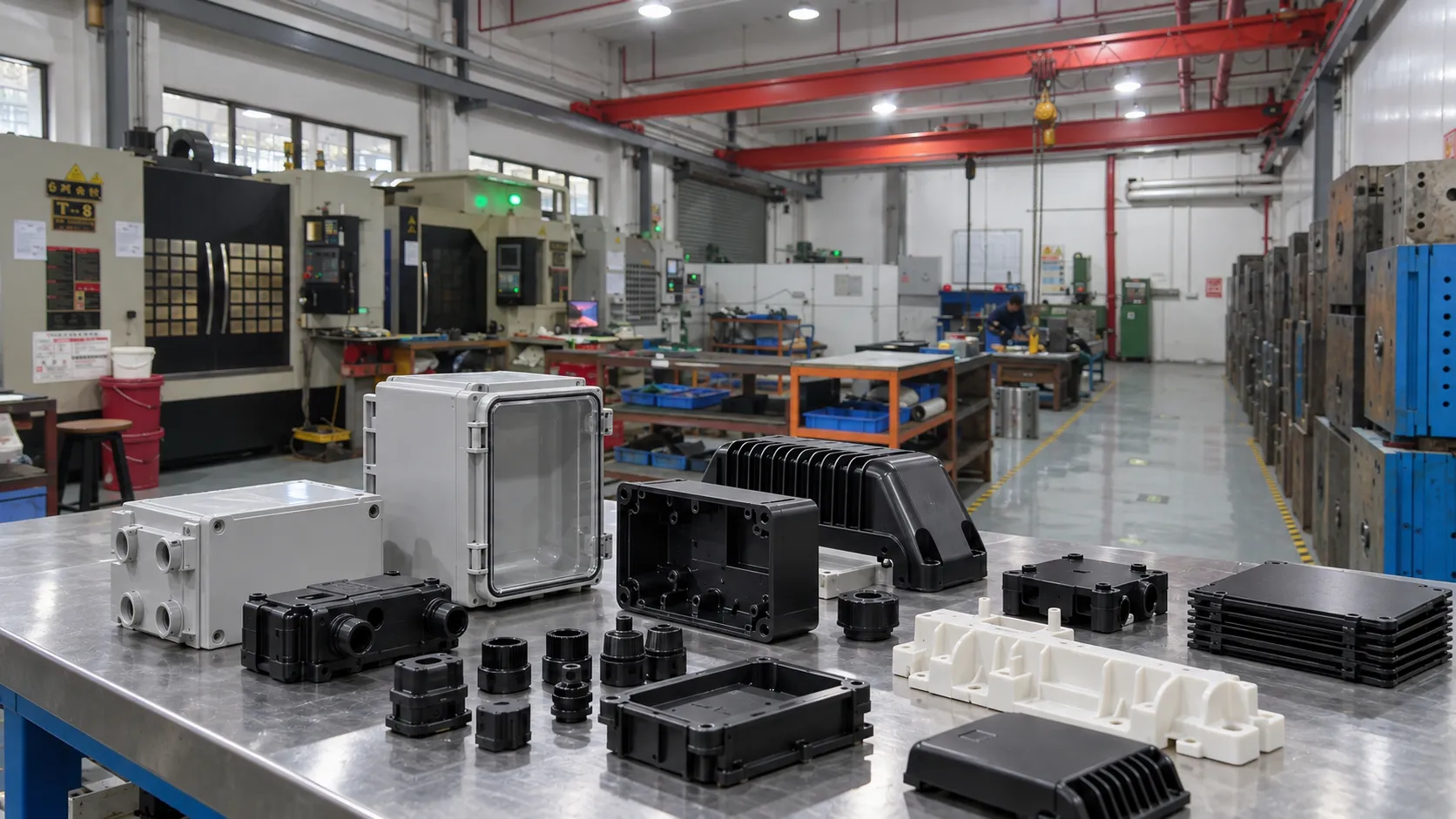







Draft is the taper applied to a surface that moves approximately parallel to the mold-opening direction. It is easy to treat draft as a cosmetic CAD detail, but its real purpose is mechanical: reduce contact and friction during ejection.
Insufficient draft can lead to sticking, drag marks, whitening, deformation, texture damage, or excessive ejector load. That is why draft is one of the first checks in a structured DFM analysis.

1. Why do molded parts need draft?
Plastic contracts as it cools. Internal walls often shrink onto the core, while external walls remain in contact with the cavity surface until the tool opens. If a deep wall is perfectly vertical, a large surface area can remain in sliding contact during ejection.
Draft increases clearance progressively as the part moves, reducing friction and the force needed to release it.
2. What controls the amount of draft required?
The main variables are wall depth, resin shrinkage, surface texture, polish, feature geometry, mold temperature, and which side of the tool must retain the part before ejection. There is no single angle that is correct for every molded feature.
| Design factor | Why it changes draft demand | Typical implication |
| Wall depth | Longer sliding contact increases friction | Deeper walls usually need more generous release conditions |
| Texture | Surface peaks resist sliding | Texture and draft must be reviewed together |
| Resin / shrinkage | Part may grip the core differently | Material behavior affects ejection force |
| Inside vs outside surface | Shrink direction changes contact | Internal walls often need closer attention |
| Functional land | Geometry may need local dimensional control | Use a short controlled land rather than zero draft everywhere where possible |
3. Why must pull direction be defined before draft analysis?
A face can show positive draft in one direction and become reverse draft or an undercut when the mold-opening direction changes. Parting-line location, core/cavity assignment, slides, and lifters therefore have to be considered together.
Early mold design input is especially useful on housings with deep pockets, connector openings, snaps, or styling features that make the natural pull direction less obvious.
4. Why do textured surfaces usually need more draft?
Texture creates microscopic peaks and valleys that mechanically resist sliding against the steel. Deeper or more aggressive texture increases this interaction, so a surface that ejects acceptably when polished may drag after texture is added.
Texture specification and draft should therefore be reviewed together. Adding texture late can turn an acceptable wall into an ejection risk.

5. How do inside and outside walls differ?
Inside walls frequently grip the core because the part shrinks inward during cooling. Outside walls may release more readily, but cosmetic drag marks can still make a small ejection defect unacceptable.
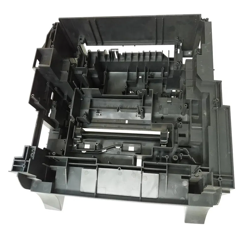
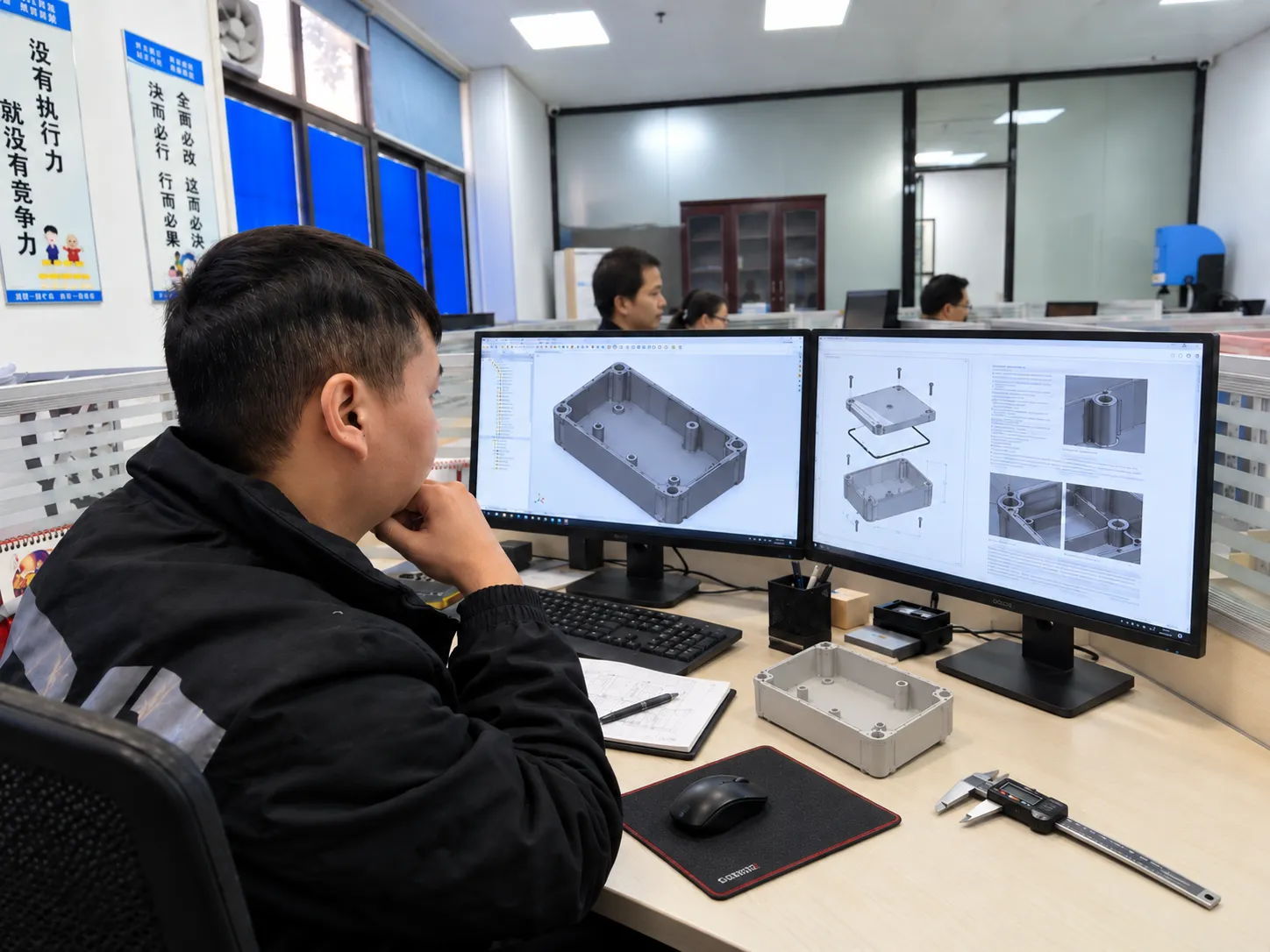
Deep box-shaped parts are particularly sensitive because total contact area becomes large. The issue is not one face in isolation; it is the combined friction of the complete shell.
6. Do ribs, bosses, and internal features also need draft?
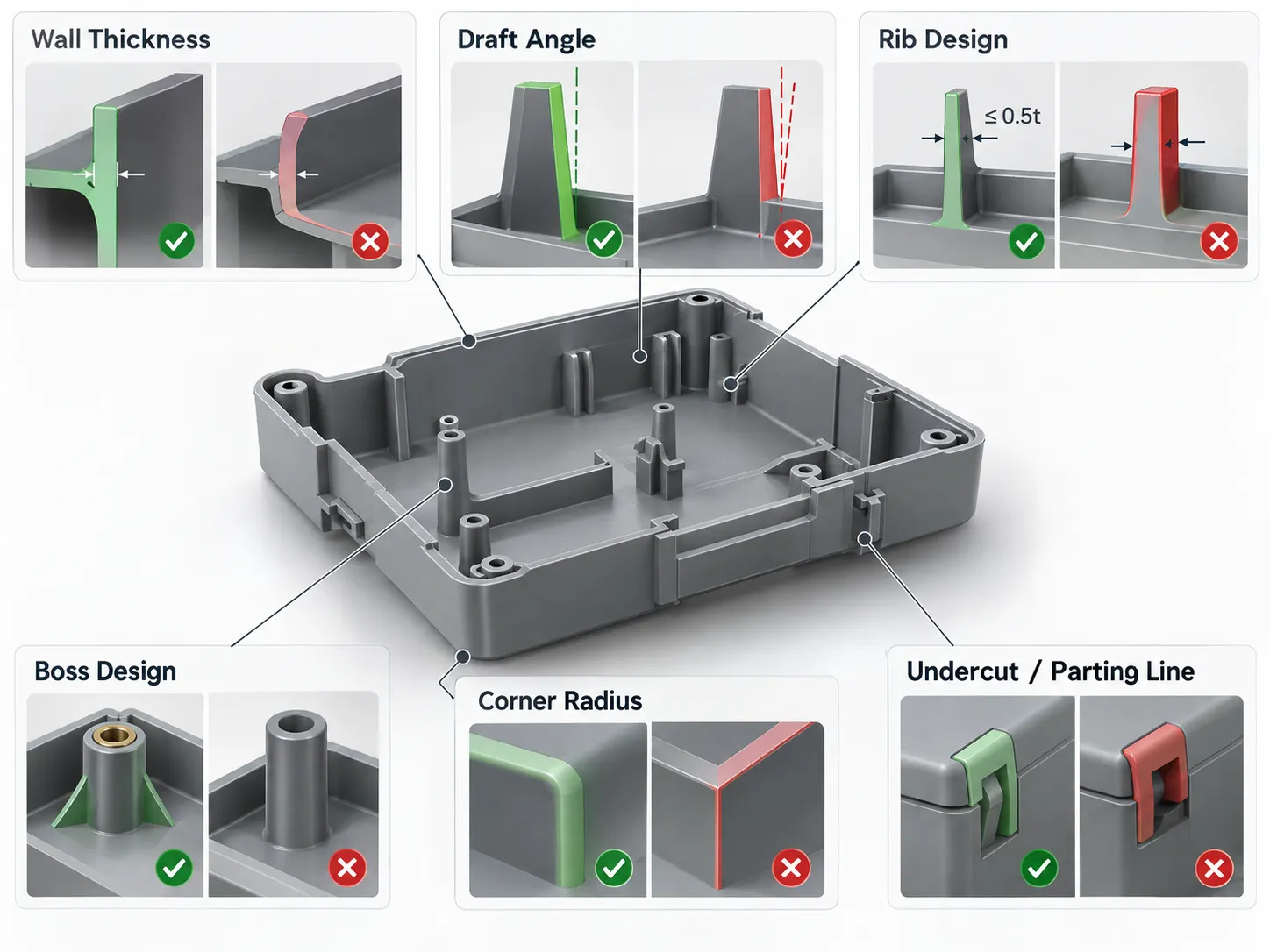
Yes. Ribs, gussets, bosses, connector pockets, and other vertical features must release from steel just like exterior walls. Deep narrow ribs can be difficult to fill, vent, machine, and eject if their taper is ignored.
Draft on internal features should be reviewed together with ejection and mold manufacturing feasibility rather than applied only to the visible exterior.
7. What if a functional surface appears to require zero draft?
First identify how much of the surface is truly functional. Often a short land controls the fit while the remaining depth can be tapered. This preserves the critical interface without forcing the entire wall to be vertical.
Where near-zero draft is genuinely required, the tooling solution may need polished steel, controlled ejection, side action, or another intentional method. The exception should be documented instead of left as an unexplained CAD condition.
8. How does draft affect dimensional measurement?
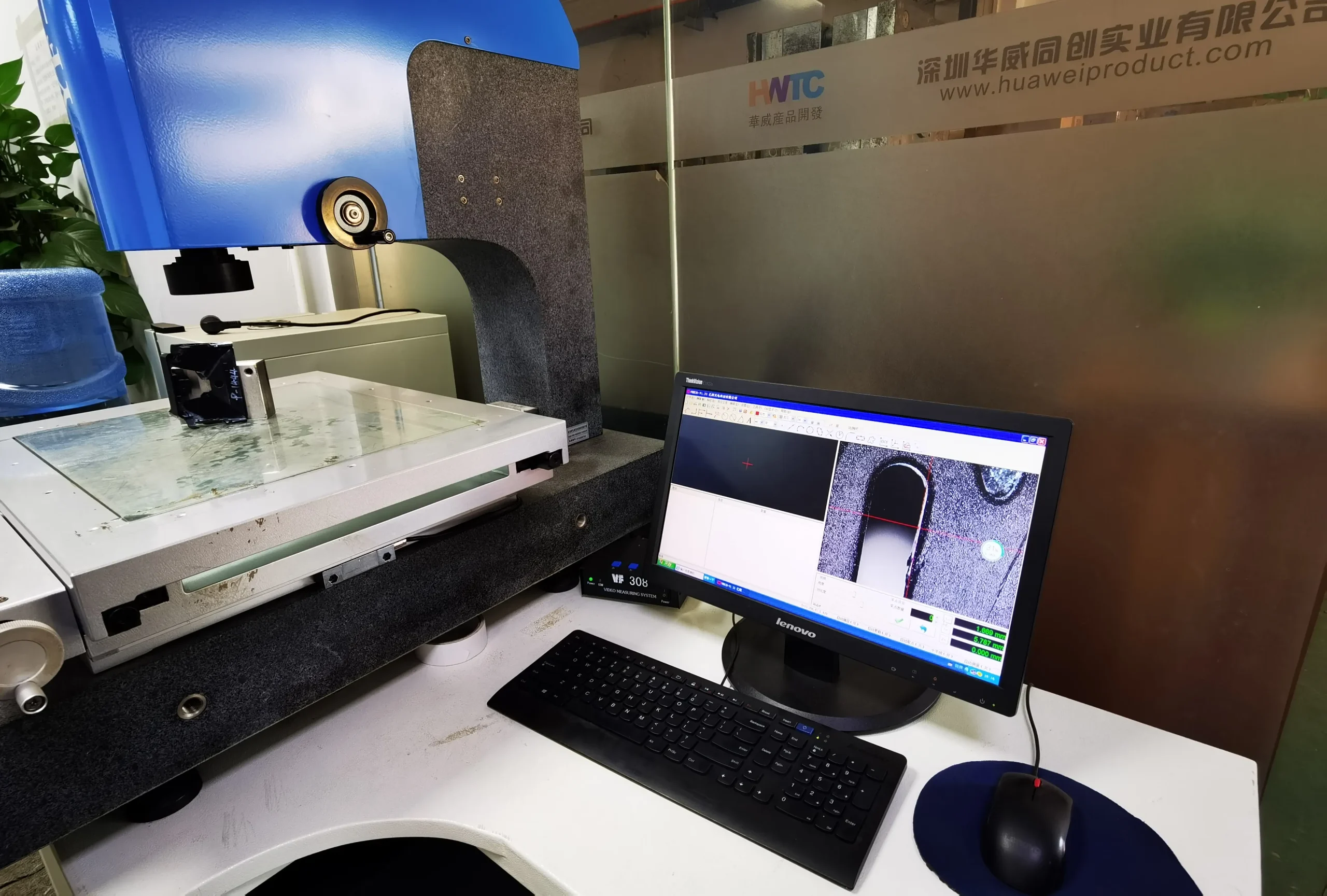
A drafted wall has different dimensions at different heights. Drawings should therefore define where a critical width, diameter, or gap is measured rather than referring only to the nominal CAD size.
This matters for inspection because measuring at a different height can create an apparent dimensional disagreement even when the mold is correct.
9. When should draft analysis be repeated?
Repeat it after major geometry changes: parting-line moves, deeper pockets, added texture, new snaps, wall-height changes, rib changes, or revised pull direction.
The model should be checked again before final release to injection molding tooling, and deliberate zero-draft exceptions should remain documented through revision changes.