


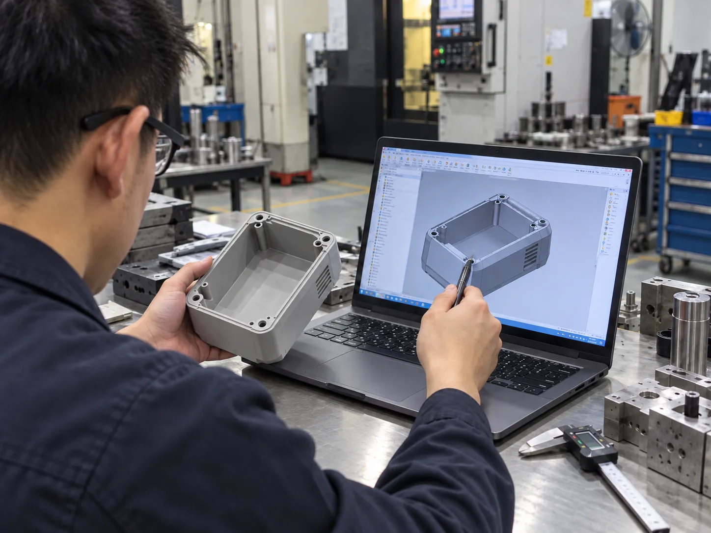
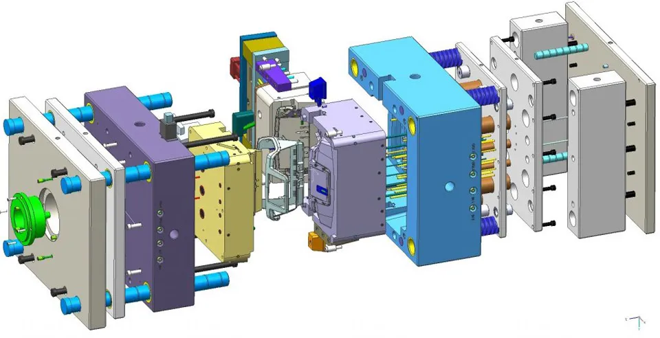
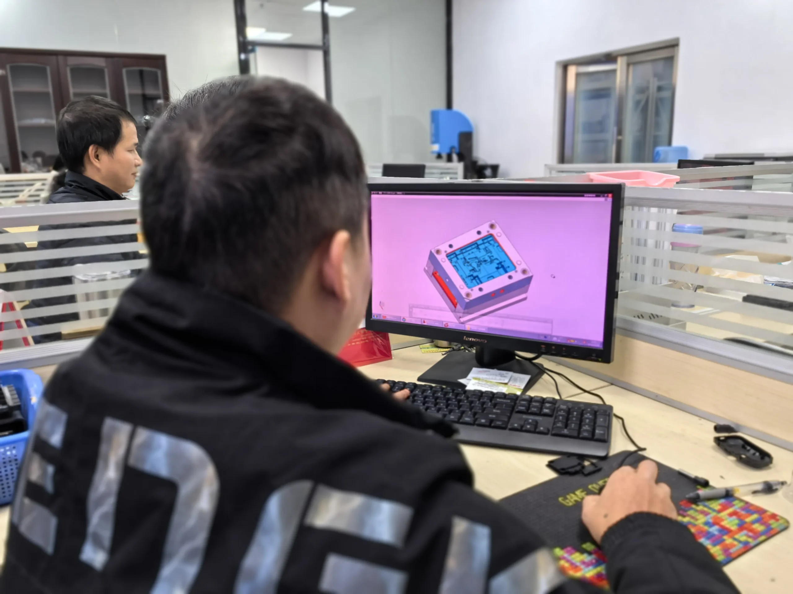





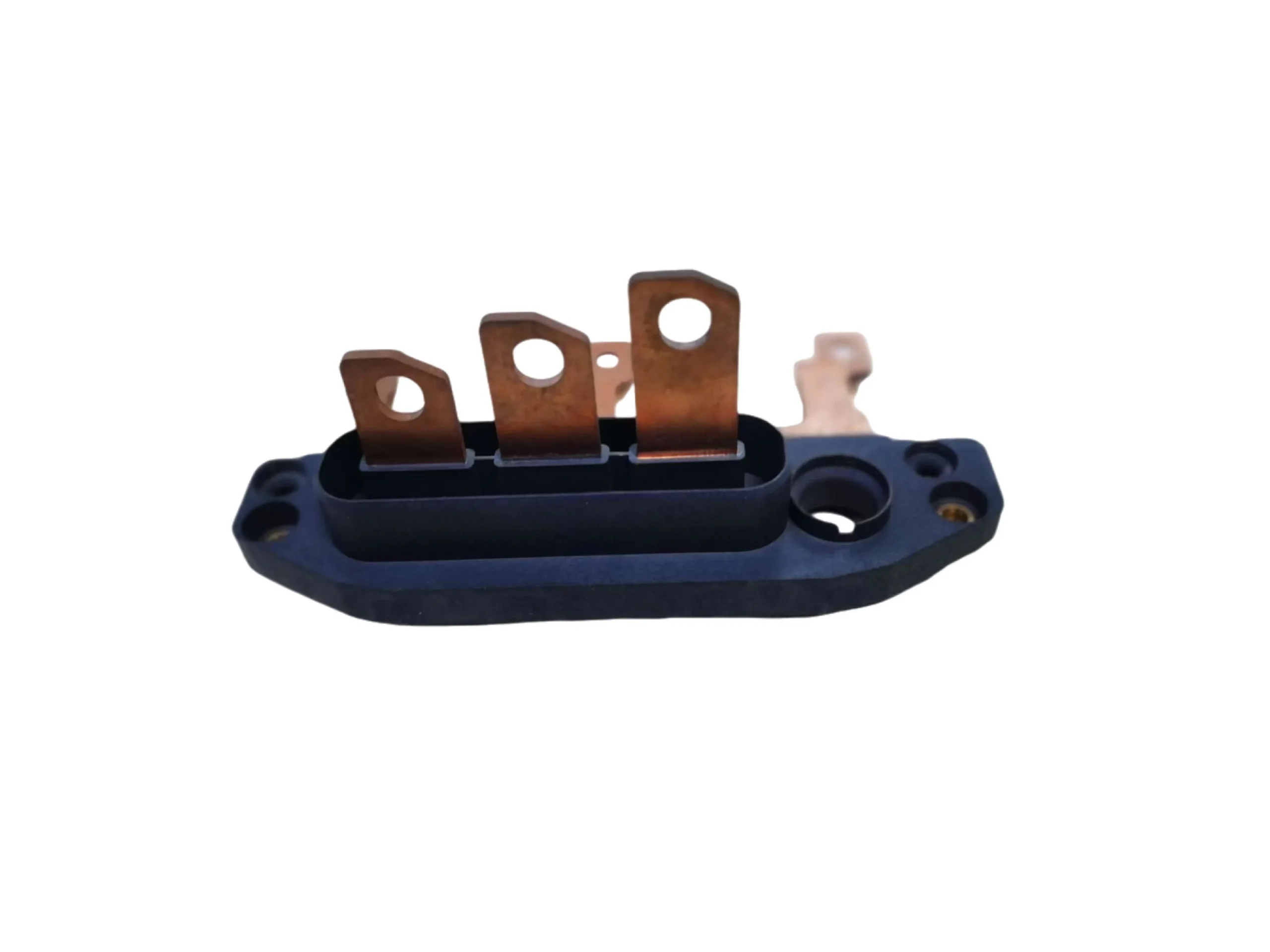

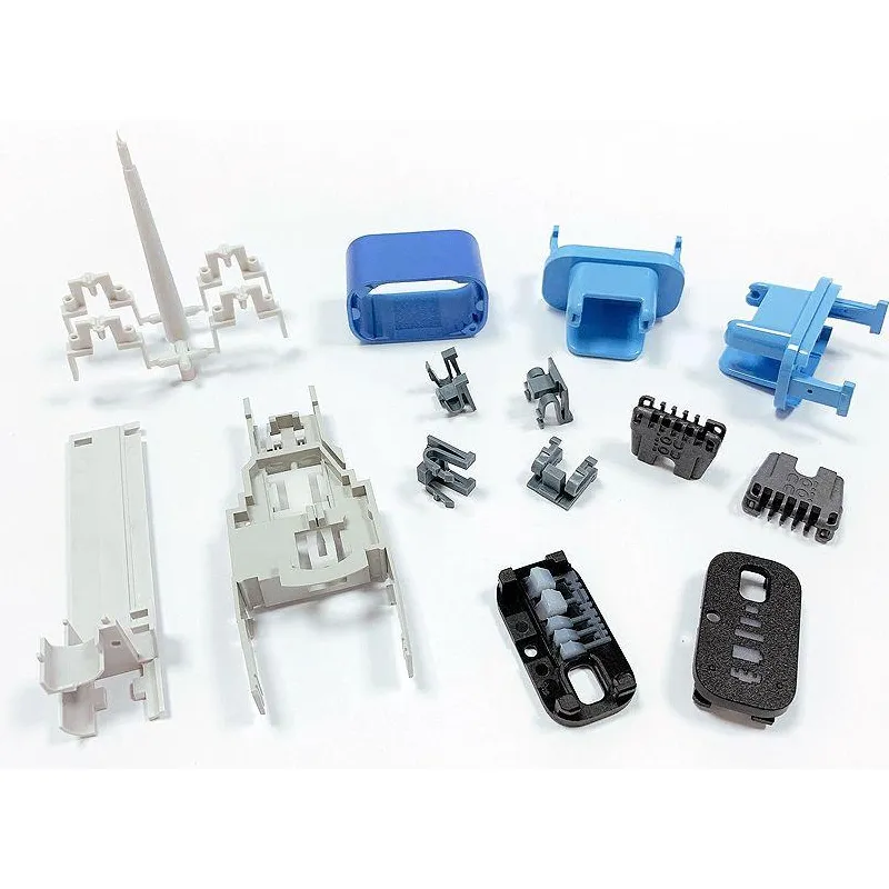
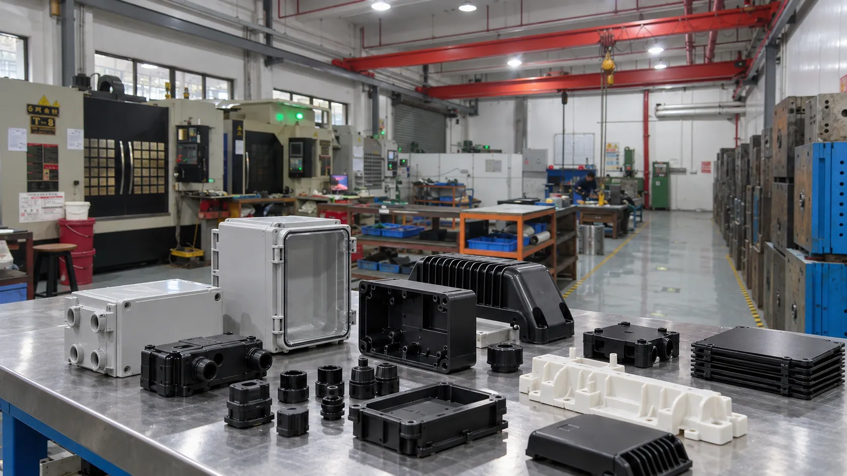







An injection gate is small compared with the molded part, but it controls the first boundary condition of cavity filling. A gate that is easy to machine may place a weld line in a loaded feature. A small cosmetic gate may create excessive shear or pressure loss. A wide gate may improve packing but leave a larger witness mark.
For that reason, gate decisions belong in both DFM analysis and mold design rather than being postponed until the product geometry is already frozen.

1. What must an injection gate accomplish?
A gate must deliver enough molten material to fill the cavity, support packing while the material cools, freeze predictably, and release or separate in a controlled way. At the same time, it should respect appearance surfaces, structural features, automation, and trimming requirements.
The correct gate therefore depends on resin viscosity, wall thickness, flow length, cavity layout, cosmetic zones, production volume, and how the part is handled after molding.
2. How do common gate types compare?
Each gate type creates a different balance between process stability, appearance, tool complexity, and degating.
| Gate type | Main advantage | Typical consideration |
| Edge gate | Simple, robust, easy to machine and modify | Visible edge witness and runner trimming |
| Pin/point gate | Small entry point and possible automatic separation | Higher shear and sensitivity to gate size |
| Tunnel/submarine gate | Automatic degating below/near parting line | Requires controlled break-off and suitable material behavior |
| Fan/tab gate | Spreads flow into broad or thin sections | Wider gate area and more trimming |
| Hot tip / valve gate | Direct gating, lower cold-runner waste, sequential control possible | Higher tool and maintenance complexity |
3. Why does gate location matter more than gate type alone?
Gate location defines the main flow direction. It determines which regions fill first, where pressure is transmitted during packing, and where separate flow fronts may meet.
A technically acceptable edge gate can still be a poor choice if it directs flow around a hole and creates a weld line at a snap, screw boss, hinge, or sealing feature.
4. How does gate location influence weld lines?
Weld lines form where flow fronts meet after passing around a core, hole, insert, or separate flow path. Their position should be reviewed against structural load, appearance, sealing, and electrical or assembly requirements.
Moving the gate can move the weld line, but it can also change pressure, orientation, venting demand, and warpage. Gate changes should therefore be evaluated as a system change, not a cosmetic fix.

5. How does gating affect warpage and fiber orientation?
Flow direction influences molecular and fiber orientation. Reinforced materials can shrink differently parallel and perpendicular to flow, so changing gate position can change the distortion pattern even when the nominal part geometry is unchanged.
This is one reason complex parts may need a combination of flow analysis and practical mold manufacturing experience rather than a single rule of thumb.
6. When are hot runners or valve gates justified?
Hot runners reduce cold-runner waste and can gate directly into larger or multi-cavity parts. Valve gates add mechanical control over gate opening and closing and can support sequential filling or more controlled appearance on large components.
The trade-off is greater tool cost, thermal-control complexity, maintenance, and process dependency. Their value is strongest when the production requirement actually benefits from those capabilities.
7. What changes in multi-cavity molds?
Multi-cavity tools require attention to runner length, pressure loss, thermal balance, cavity-to-cavity variation, and gate consistency. A layout that appears symmetrical in CAD can still fill unevenly because of local temperature, venting, machining variation, or runner behavior.
During injection molding trials, compare part weight, fill sequence, appearance, and pressure cavity by cavity instead of judging only the complete shot.
8. How should gate design be verified during T0/T1?
Short-shot studies can reveal the real filling sequence. Trial data should also review part weight, peak pressure, weld-line location, gate freeze behavior, gate vestige, and cosmetic effect.
Where possible, design the initial gate with safe tuning allowance. A controlled gate adjustment after real trial evidence is often more reliable than trying to predict the final gate dimension from CAD alone.
9. Gate design checklist before steel is finalized
Confirm the acceptable gate-witness area, likely weld-line zones, flow direction, venting strategy, runner balance, packing path, degating method, automation requirement, and whether the gate can be safely tuned after the first trial.
For bridge tooling or low-volume injection molding, adjustability may be more valuable than an optimized high-complexity gate system intended for long-run automation.