

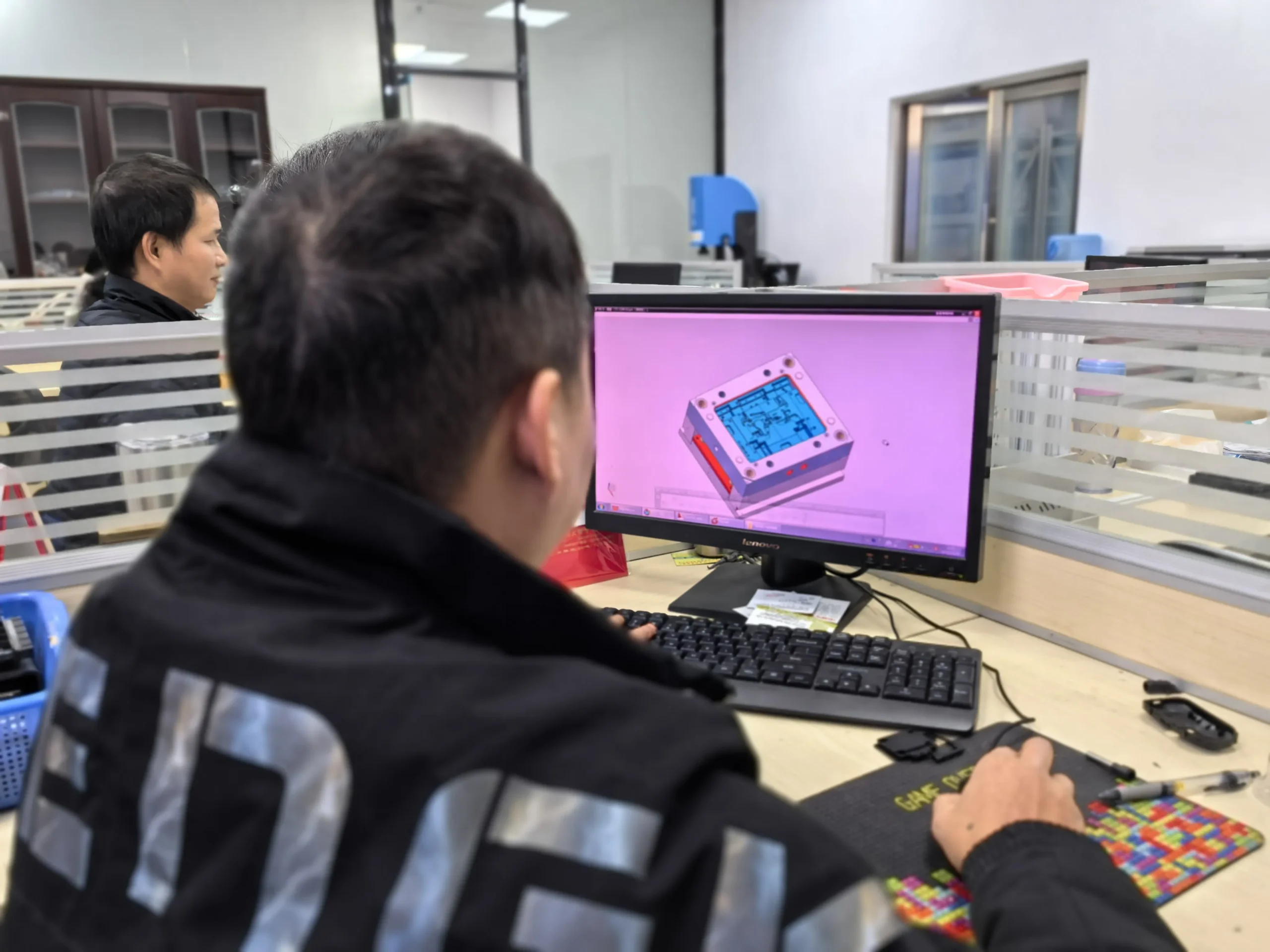



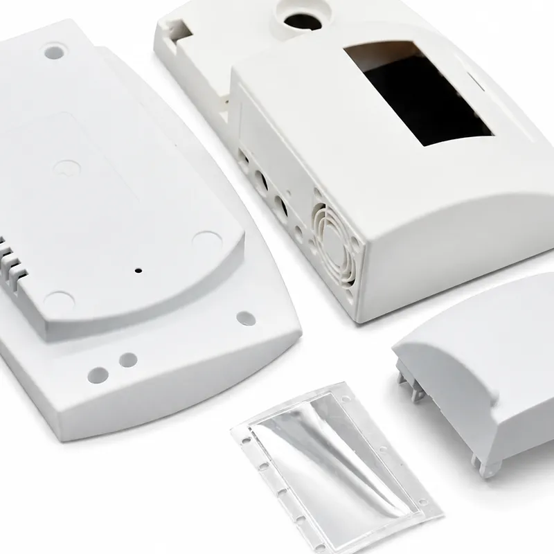
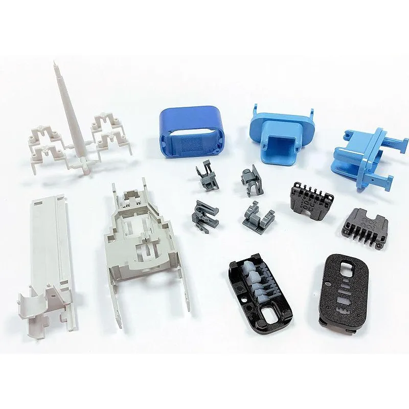
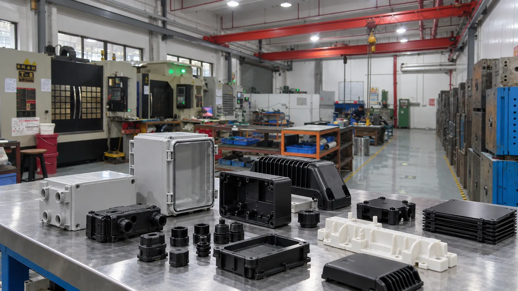
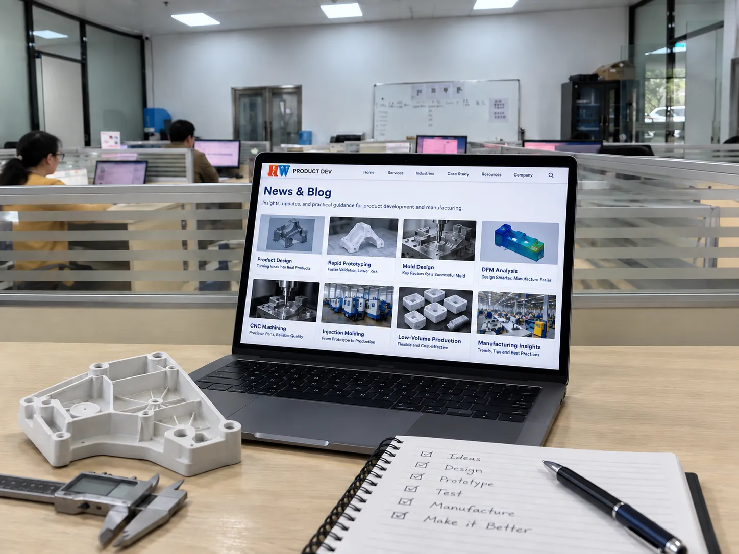

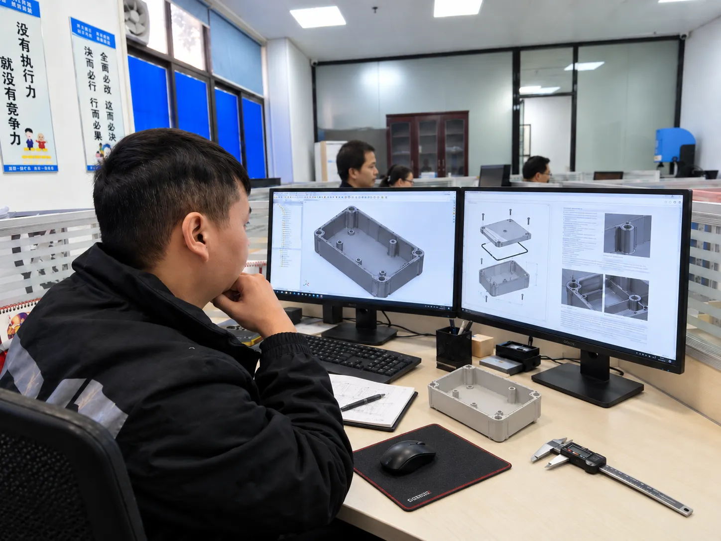


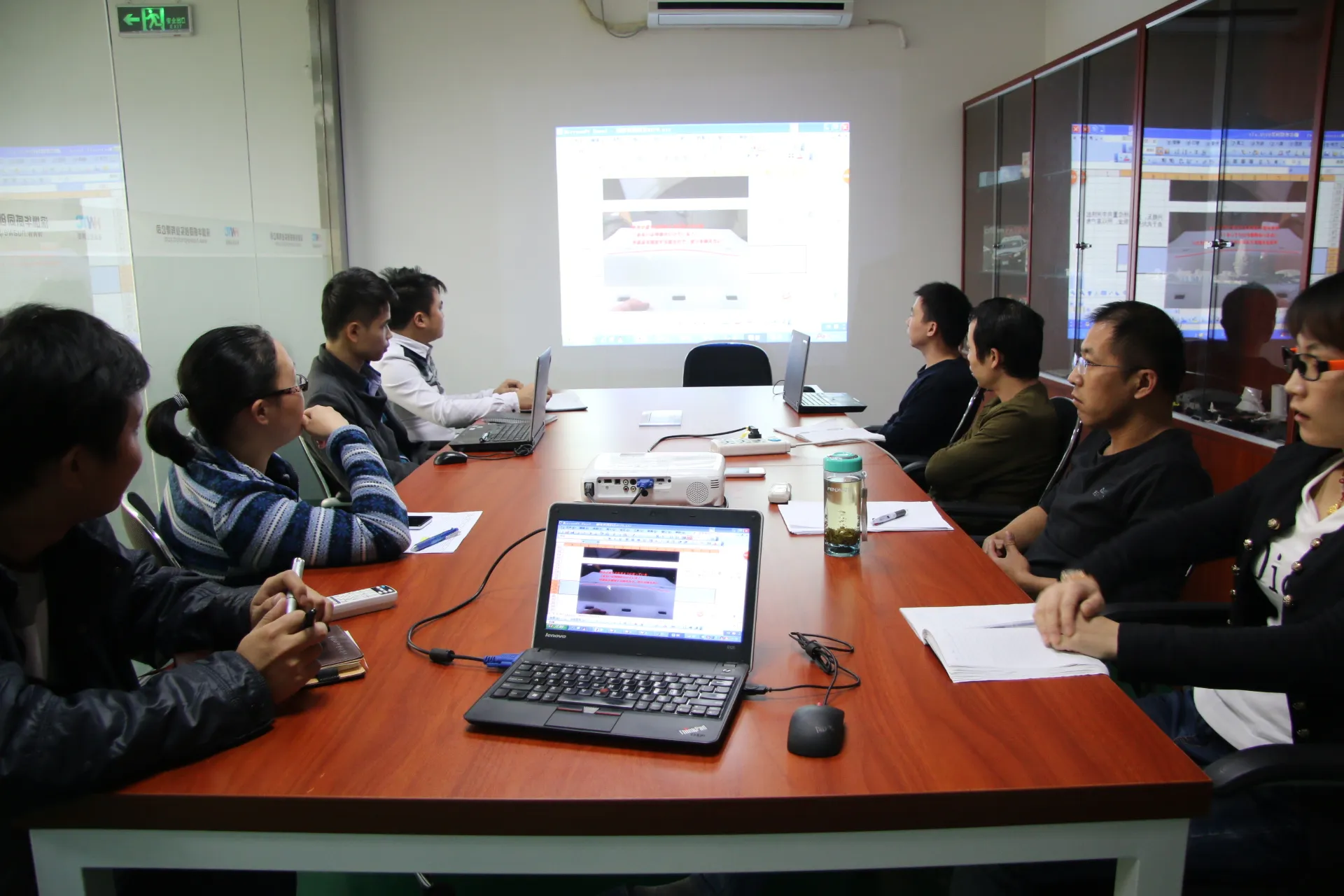


A CAD model can be complete enough for a design review and still be incomplete as a manufacturing input. That difference is where many DFM discussions become slow. The supplier asks which surface is cosmetic, which dimensions are critical, what resin will be used, whether the assembly is frozen, and which revision is current. None of those questions means the CAD is “bad.” They mean the file does not yet contain enough manufacturing context.
| Key idea: CAD complete ≠ tooling ready. A useful DFM package reduces ambiguity before anyone starts deciding gates, parting lines, sliders, cooling, or steel. |

1. What is a DFM review actually trying to decide?
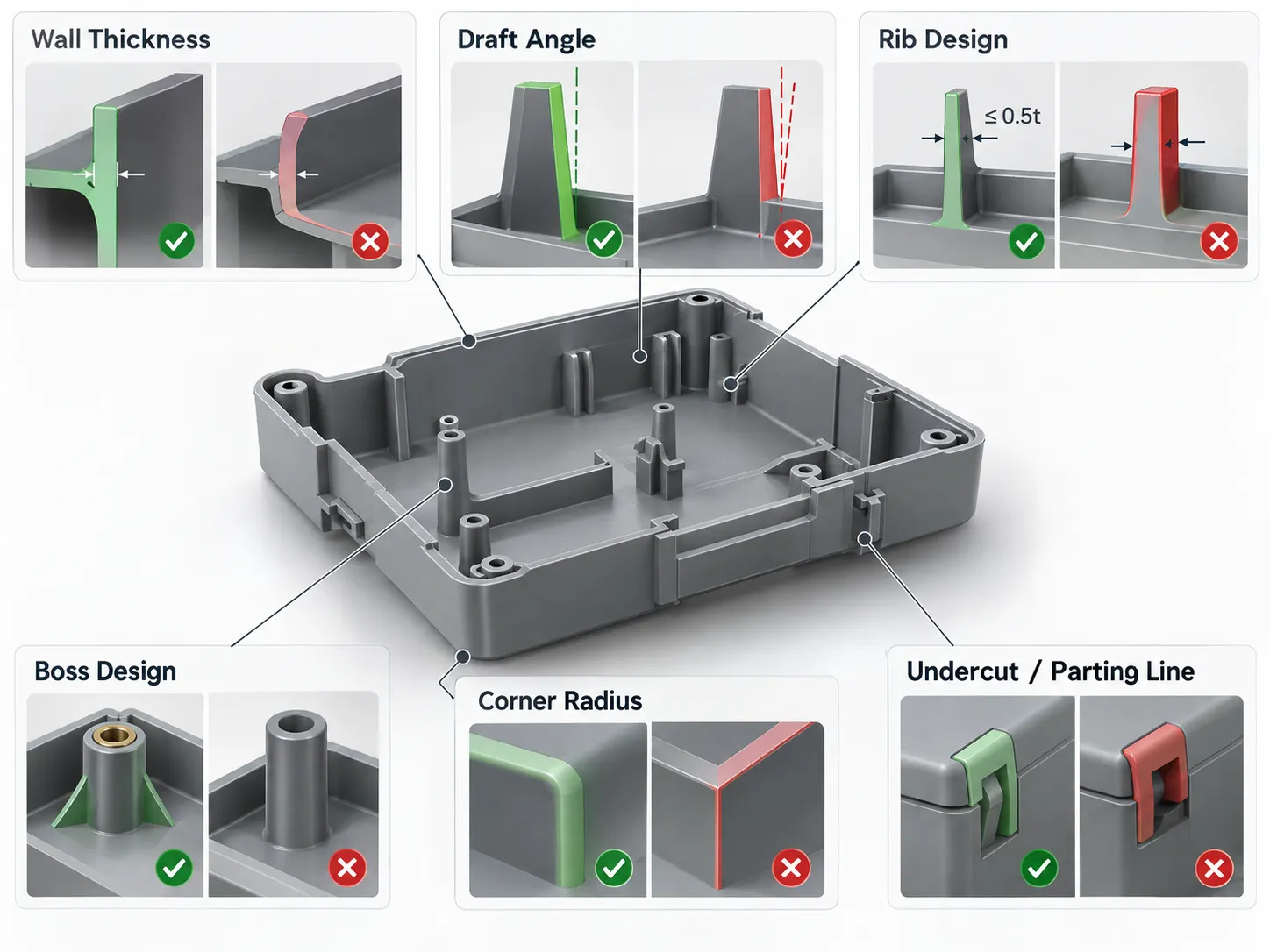
A useful DFM analysis is not a generic checklist added after design. It is the point where product intent is translated into manufacturing constraints. The review should answer a few concrete questions: Can the part release from the mold? Are wall transitions likely to create sink or distortion? Which features need side actions? Which dimensions drive assembly? Which surfaces can accept a gate, ejector witness, or parting line?
The goal is not to eliminate every manufacturing challenge. The goal is to make each challenge visible early enough that the team can choose whether to change the product, change the tooling concept, or accept the trade-off.
2. Why does a clean 3D model still create repeated questions?
Because geometry is only one layer of product definition. A mold designer can see a boss, but cannot know whether it is a critical locator. A supplier can see a textured exterior, but cannot know whether a witness line is acceptable near the edge. A nominal wall thickness may look reasonable, but the selected resin, cosmetic requirement, and flow length may change the risk.
Before sending the package, treat the CAD as one part of a small information system: 3D geometry + drawing or CTQ list + material + surface requirements + assembly context + revision status. The more clearly those pieces agree with each other, the less time is spent resolving contradictions.
3. Which geometry should you check before asking for tooling feedback?
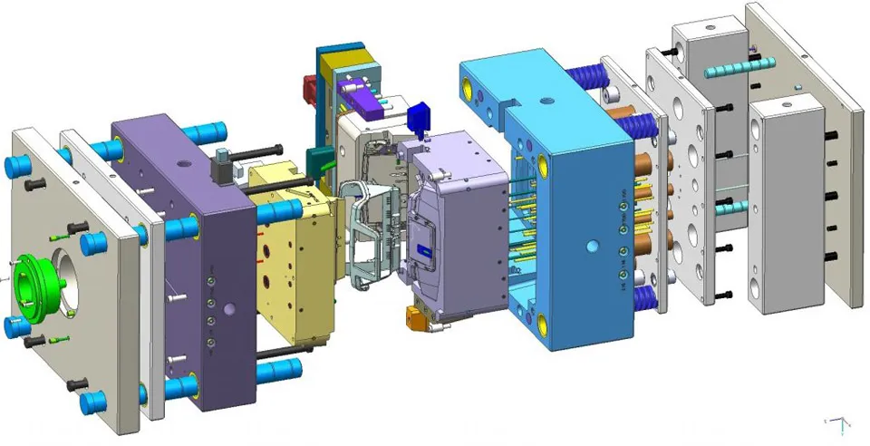
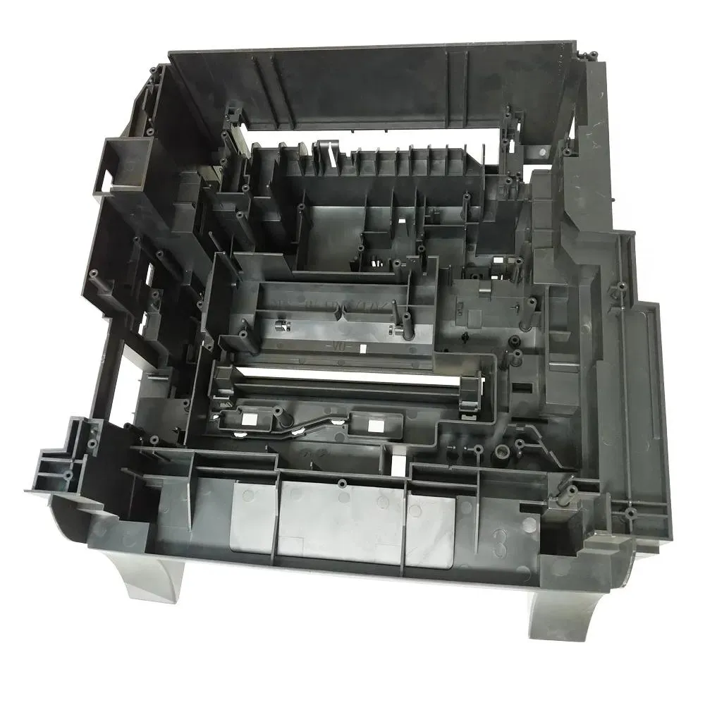
Start with the features that can change the mold architecture rather than minor dimensions. Check the primary pull direction, obvious undercuts, deep ribs, shutoff areas, thin steel conditions, abrupt wall transitions, tall bosses, snap hooks, and sealing features. These are the details most likely to affect side actions, parting-line strategy, ejection, cooling, and mold strength.
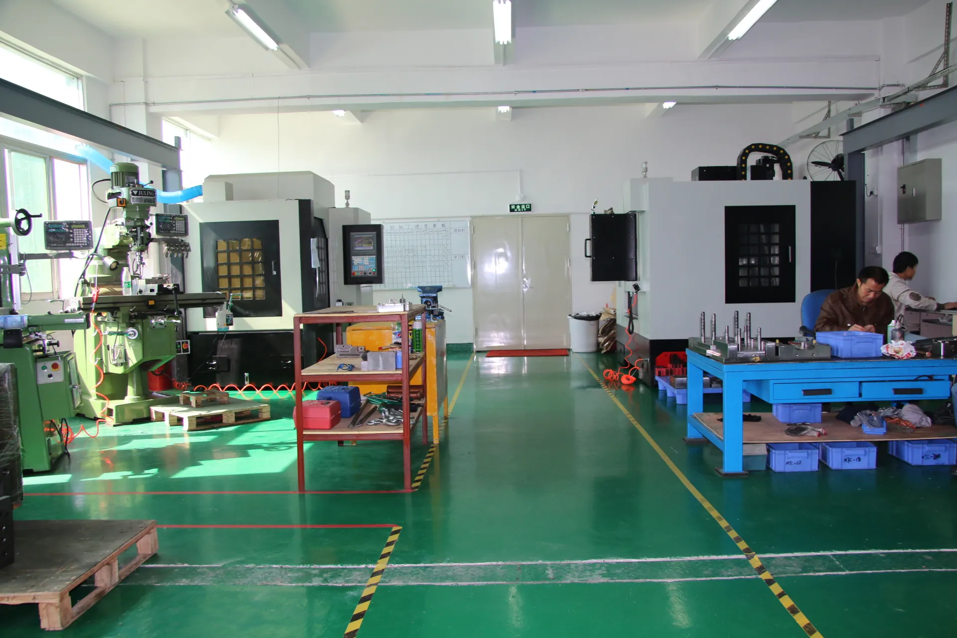
At this stage, it helps to think from the mold design side: if this feature cannot be machined, vented, cooled, or released reliably, what mechanism would be required to make it? That question turns an abstract “DFM issue” into a cost, risk, and maintenance decision.
4. Which dimensions should be treated as CTQs?
Do not label every dimension as critical. That makes the word “critical” meaningless. A CTQ should connect to fit, function, safety, sealing, appearance, or downstream assembly. Typical examples include connector positions, snap engagement, gasket lands, bearing fits, mounting datums, gap-and-flush interfaces, and dimensions that control a stack-up.
For each CTQ, define the datum reference, measurement method if known, and the real functional reason for the tolerance. A mold maker can then judge whether the tolerance is realistic for the material, part size, shrink behavior, and tool concept instead of simply receiving a number with no context.

5. Why should material and cosmetic requirements be frozen early?
Material changes can alter shrinkage, flow, stiffness, warpage, surface appearance, and processing temperature. A late switch from one resin family to another can make earlier tooling assumptions less reliable. The same applies to texture and gloss: a surface that looks identical in CAD may require different draft or polishing depending on the finish.
If material selection is still open, resolve the functional requirement first through engineering assistance or prototype testing rather than forcing the mold design to absorb an unknown. Where appearance is important, mark A-surfaces and no-gate/no-ejector zones directly in the design package.
6. What should you send with the CAD file?
A compact DFM package is usually more useful than a long email thread. Include:
- current STEP / Parasolid / native CAD revision
- 2D drawing or CTQ list with datum scheme
- target resin and any approved alternatives
- color, texture, gloss, and cosmetic zones
- mating parts or assembly references
- expected production volume and any known tooling constraints
- a short list of open questions that still require engineering judgment
7. When is the design ready to move from DFM into tooling?
Not when every line in the DFM report is green. It is ready when the remaining risks are understood, assigned, and intentionally accepted. Some items belong in product design, some in tooling, and some in process development. The important thing is that they are not hidden.
If the project still needs physical confirmation of clips, interfaces, sealing, ergonomics, or assembly sequence, use a rapid prototype to answer those questions before committing to steel. A prototype is most valuable when it closes a specific uncertainty rather than simply reproducing the CAD.
What a good outcome looks like
A good DFM handoff does not try to prove that the design is perfect. It makes the design understandable. If a mold designer can identify the pull direction, critical interfaces, material behavior, cosmetic limits, and unresolved risks without guessing, the review becomes faster and the later tooling decisions become easier to trace. The practical test is simple: if the manufacturing team has to keep asking what the product is supposed to do, the package is not finished yet.