

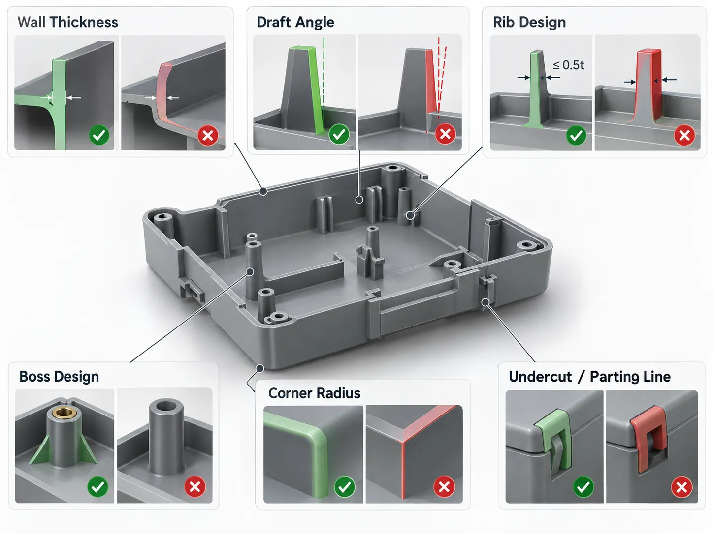



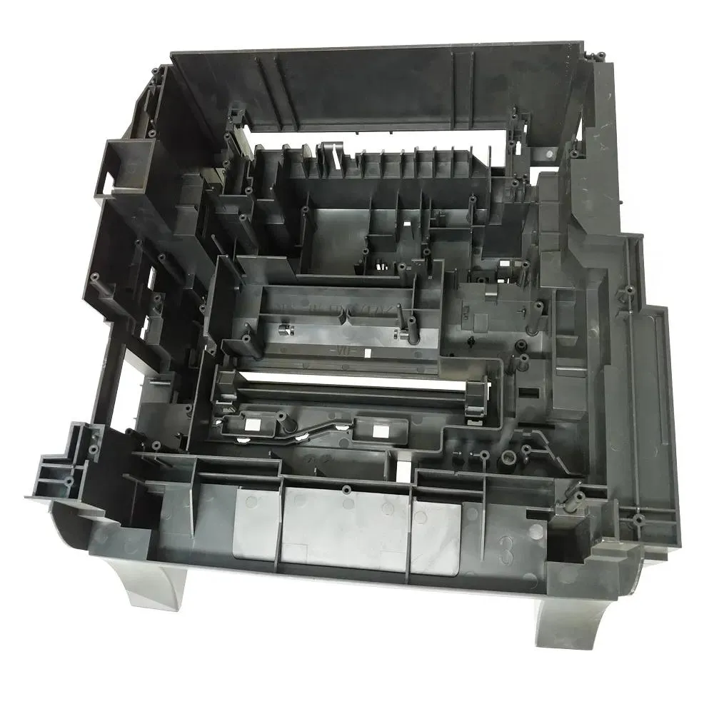
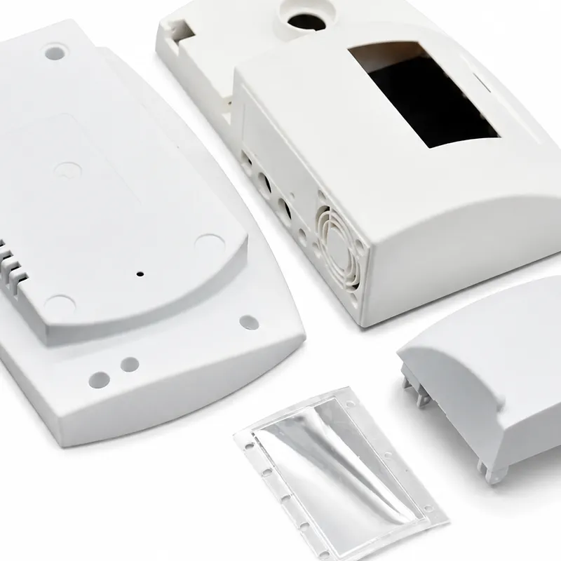
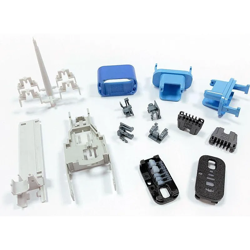

Ribs and bosses are structural features, but their manufacturing effects are often visible on the opposite side of the part. A rib that is too heavy can create sink. A boss placed beside a cosmetic wall can form a hot spot. A dense feature cluster can distort the housing even when every individual feature looks reasonable.
A useful DFM analysis therefore reviews ribs and bosses as part of wall thickness, flow, cooling, ejection, and assembly—not as isolated CAD details.

1. Why use ribs instead of simply making a wall thicker?
Ribs can increase bending stiffness more efficiently than adding material uniformly across a panel. Thickening the complete wall increases material use and cooling time and creates larger shrinkage differences.
The goal is to place material where it supports the load path without turning the part into a collection of heavy intersections.
2. Why does rib base thickness matter?
The rib base joins the nominal wall and is the region most likely to create a heavy section. If too much material accumulates there, the opposite surface can show sink or the region can cool more slowly than the surrounding wall.
For appearance-critical housings, the rib-to-wall transition should therefore be reviewed against surface finish, resin behavior, and expected process conditions.
3. What do draft and radius do on a rib?
Draft allows the rib to release from the mold. A base radius reduces stress concentration and helps flow enter the feature. Both are useful, but both affect local thickness.
During mold design, the engineer must balance structural benefit with steel strength, machining access, venting, and ejection.
4. Why are tall isolated ribs risky?
Very tall thin ribs can be difficult to fill and may require slender steel features that are harder to machine, vent, cool, and protect. A tall isolated rib can also concentrate load without providing a stable structural path.
Where possible, distribute stiffness through a rib network, gussets, or revised section geometry rather than depending on one extreme feature.
| Feature | Primary purpose | Common risk if overdone |
| Rib | Increase stiffness | Sink, difficult filling, thin tool steel |
| Gusset | Support a boss or wall junction | Local thickness and cooling hot spot |
| Screw boss | Fastening / location | Sink, cracking, poor access, weld line |
| Insert boss | Carry threaded insert loads | Stress, insert movement, knit-line risk |
| Dense rib network | Distribute load | Heat accumulation, ejection and venting complexity |
5. How should a screw boss be supported?
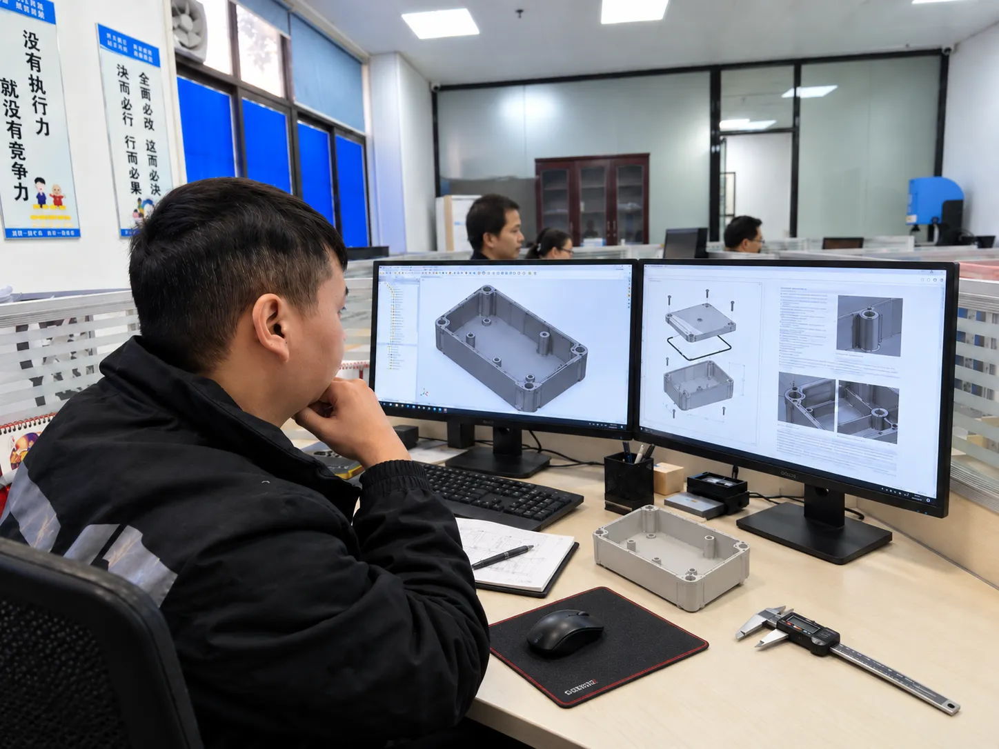
A boss must carry assembly force and service load without creating an unnecessarily thick mass. A controlled boss wall supported by ribs or gussets is often more efficient than simply increasing the boss diameter or wall thickness.
Fastener type, pilot hole, tightening torque, service cycles, and access should be defined before the boss geometry is frozen.

6. What changes when metal inserts are used?
Heat-set inserts need enough surrounding plastic to resist installation and service loads. Molded-in inserts add another requirement: the tool must position the insert and allow plastic to flow around it without moving it or creating unacceptable knit lines.
Anti-rotation geometry, insertion direction, pull-out or torque requirement, and critical position should be defined early because they affect both boss geometry and tooling.
7. Why do bosses create weld-line concerns?
A boss or through-hole divides the melt flow. The flow fronts join again downstream, creating a weld line. If that region carries high stress or must seal, gate location and boss orientation may need to change.
This connects part structure directly with the injection molding filling pattern rather than treating gate design and boss design as separate topics.
8. How should ribs and bosses be checked for assembly?
Screws need driver access, mating parts need clearance, and tolerance stack-up must allow the assembly to locate without forcing the plastic structure. A feature that molds well but creates awkward assembly is not a finished design.
A rapid prototype can confirm access, fit, and basic function, but it does not reproduce molded shrinkage, sink, or weld-line behavior exactly.
9. Why do dense feature clusters need cooling and ejection review?
Several bosses, ribs, and gussets close together can create a local hot zone. Even if each feature is individually acceptable, the cluster can cool more slowly and shrink differently from the surrounding wall.
Tool designers may need dedicated cooling, different core construction, venting, or material removal. The feature layout must also leave robust surfaces for ejector placement without marking appearance-critical areas.
10. Final rib and boss review checklist
Before tooling, check base thickness, draft, radii, rib height, boss support, fastener access, insert requirements, weld-line position, cooling density, and ejector access. The objective is not to maximize the number of ribs; it is to create the required stiffness and assembly function with a geometry that can be molded repeatedly.