






When a molding defect appears, the fastest reaction is often to change pressure, temperature, speed, or cooling time. Sometimes that works. The problem is that the improvement may only hide the real cause, narrow the process window, or create a different defect. A useful troubleshooting method starts one level higher: first identify which family the cause belongs to—material, product geometry, mold, or process.
| Key idea: Defect symptom ≠ root cause. The same visible defect can come from different systems, so the correction should follow evidence rather than habit. |

1. What should be proven before troubleshooting starts?
Prove that the defect is repeatable. Collect consecutive parts after the mold and process have stabilized. Track cavity number on multi-cavity tools. Note whether the problem is constant, intermittent, or tied to a specific cavity. Compare part weight, defect location, cycle history, and material lot when useful.
A defect that always appears in one location suggests a different path from a defect that moves from shot to shot. Pattern is evidence.
2. Why should material be checked before tool changes?
Resin grade, moisture, regrind percentage, colorant, lot variation, and drying history can change flow, shrinkage, surface quality, and mechanical behavior. If the actual material differs from the material used during development, the process may be compensating for a different input.
When material performance and manufacturability are in conflict, resolve the requirement through engineering assistance before using extreme settings to force the resin through the mold.
3. What does a short shot tell you?
A short shot means the cavity did not fill completely, but it does not automatically mean “add more pressure.” Read where the flow stops. Check shot size, velocity, melt and mold temperature, transfer position, pressure limit, gate restriction, runner balance, and venting. Burn marks near the flow end may indicate trapped air rather than insufficient pressure.
If the cavity only fills near machine limits, review the flow path, gate, venting, and wall thickness with mold design rather than accepting a fragile process.
4. What causes sink marks?
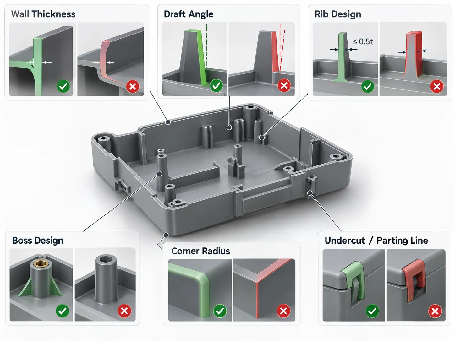
Sink is usually related to local volumetric shrinkage. Look behind the visible surface for thick ribs, bosses, pads, intersections, or abrupt wall transitions. Then review packing pressure, holding time, gate freeze, melt temperature, mold temperature, and cooling.
More packing only helps while pressure can still reach the shrinking region. If geometry is too heavy, the durable fix may be coring or a rib/boss redesign identified through DFM analysis.
5. What does warpage actually mean?
“Warped” is too vague to troubleshoot. Measure whether the part bows, twists, cups, or moves locally. Compare the deformation pattern with gate location, flow orientation, wall distribution, ribs, cooling channels, packing, and fiber orientation for reinforced materials.
Warpage is usually about differential shrinkage. The useful question is not simply how far the part moved, but which regions are shrinking differently and why.
6. Why should one cause family be changed at a time?
If speed, temperature, pressure, cooling, and material are changed together, the result may improve but the cause remains unknown. Use a small test matrix. Change one logical group at a time within safe process limits and record what happens to the defect, CTQs, part weight, appearance, and cycle.
This is also how a production injection molding process becomes transferable. Another technician should be able to reproduce the reasoning, not only copy one machine recipe.

7. How do you know the defect is actually solved?
Not after three good shots. Run long enough to reach normal thermal conditions and observe representative variation. Recheck the dimensions and functions that could be affected by the correction. Higher packing might reduce sink but move dimensions. Higher mold temperature might improve fill but lengthen cycle time. A cooling change might reduce one warp mode and shift another feature.
A root-cause correction is complete when the defect is controlled inside a practical process window without creating a new problem elsewhere.
8. When should troubleshooting return to product design?
When a defect can only be controlled by pushing the process to an extreme, the part may be asking the mold to compensate for geometry. Examples include very thick boss intersections that always sink, long thin flow paths that only fill near the pressure limit, or asymmetric wall structures that repeatedly distort. At that point, the right question is not “Which setting is left to try?” but “Is the design creating a process window that is too narrow for production?” Returning to product geometry may feel slower because it reopens a design decision, but it can be faster than carrying a fragile workaround into every future batch. Robust molding starts with a design that gives the process room to vary.
What a good outcome looks like
Troubleshooting becomes much easier when defects are treated as system signals rather than isolated surface problems. Prove the pattern, verify the material, study the fill or shrink behavior, separate geometry and tooling from process variables, test one cause family at a time, and confirm the correction under stable conditions. The objective is not to find the setting that makes today’s sample look good. It is to understand why the defect occurred so the process remains stable tomorrow.