




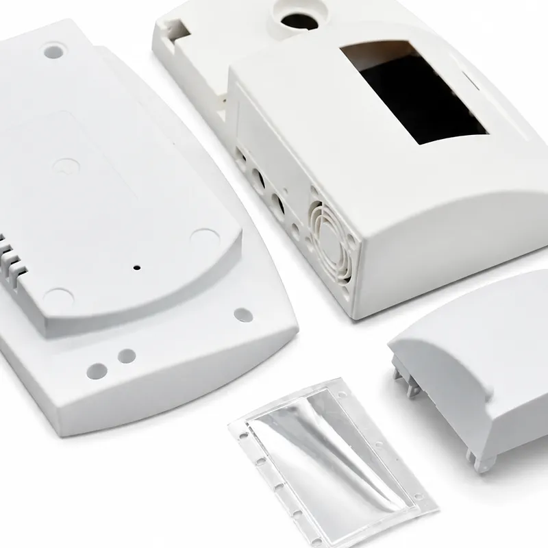
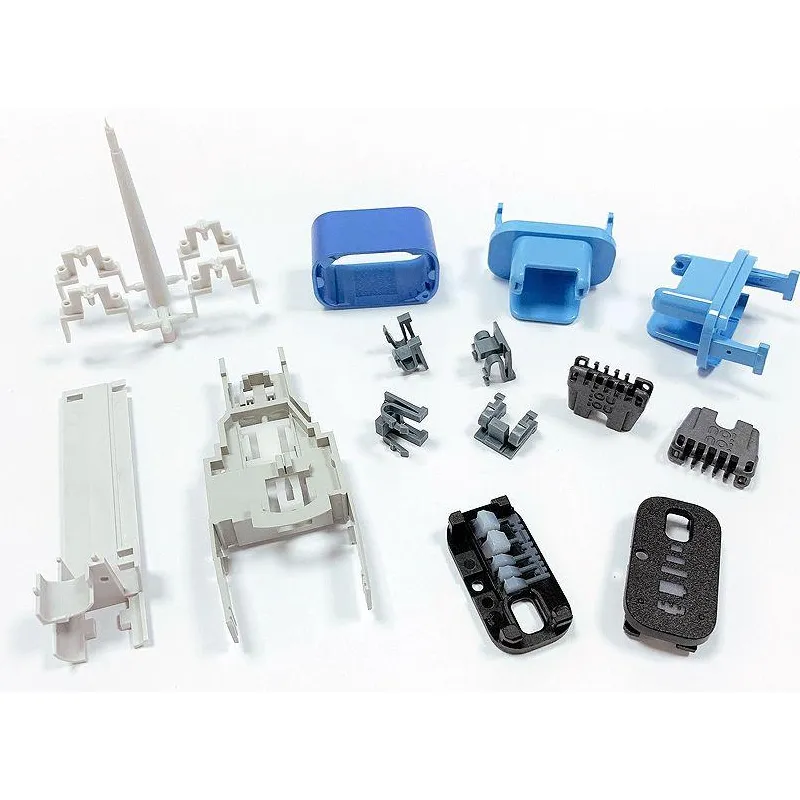
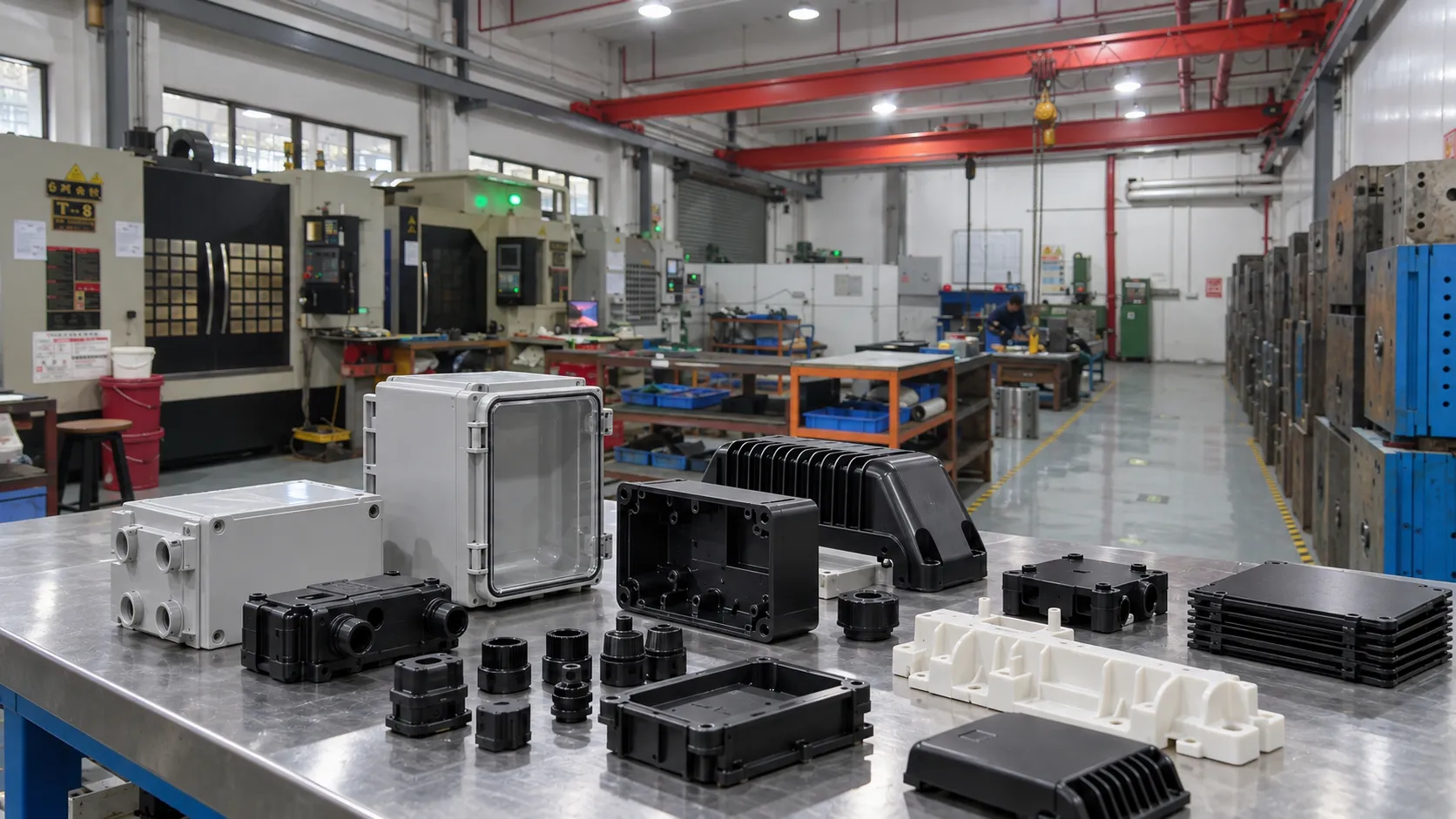
Plastic housings in robotics and AI hardware do much more than hide electronics. They locate sensors, support connectors, protect compute modules, carry sealing features, control airflow, manage impact loads, and help define the product’s perceived quality. A poorly designed cover can shift a camera, expose a PCB to dust, trap heat, or create assembly variation that appears as a software problem later. For teams developing robot arms, mobile robots, smart sensors, autonomous equipment, or edge-AI devices, robotics and AI manufacturing therefore has to connect mechanical design, materials, electronics, tooling, and scalable production.

1. Balance Stiffness and Weight
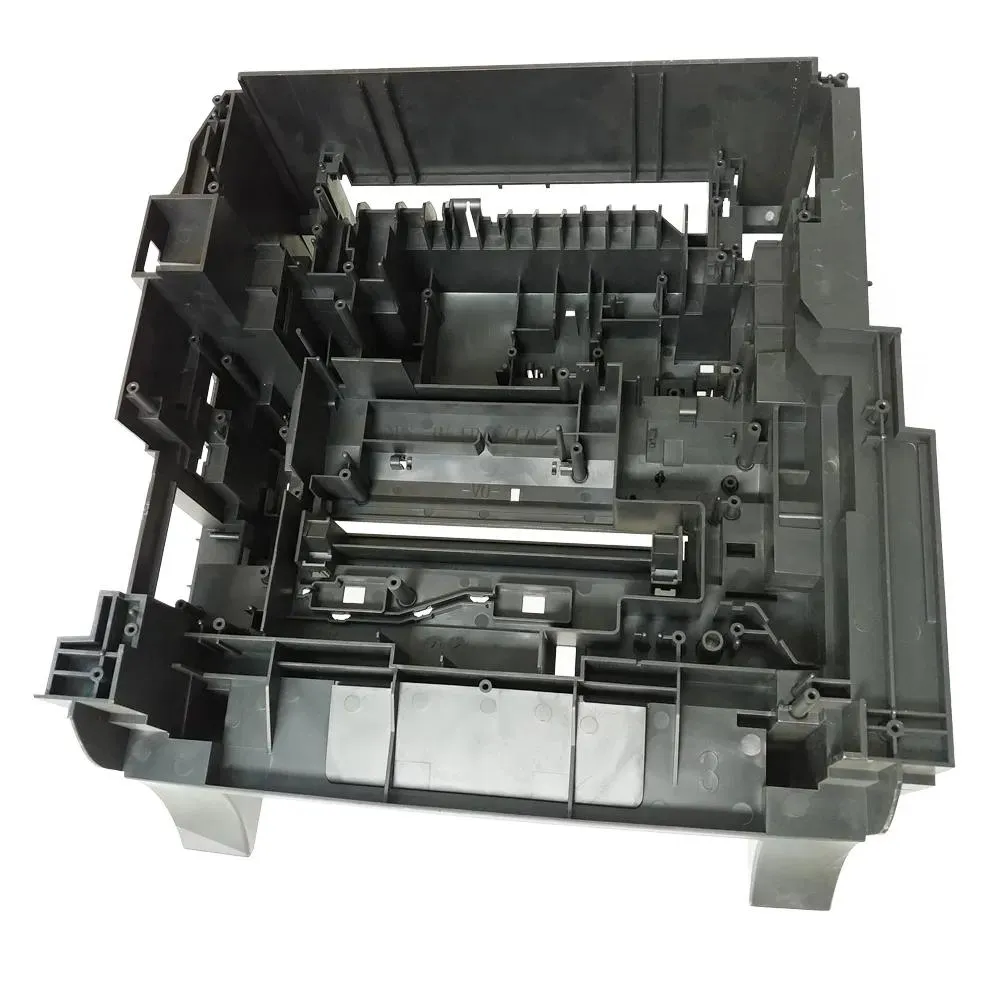
Robotic systems often benefit from low moving mass, but thin plastic without structural planning can flex enough to affect alignment or create vibration. The better strategy is to use geometry efficiently: ribs, closed sections, local gussets, curved surfaces, and controlled wall thickness can provide stiffness without simply adding bulk. Glass-filled PA or other reinforced polymers may be appropriate for structural parts, while PC/ABS or ABS may better suit cosmetic enclosures. Material stiffness must be considered together with creep, impact, humidity, processing, and the direction of reinforcing fibers in molded parts.
2. Treat Sensor Alignment as a Mechanical Requirement
Cameras, LiDAR units, proximity sensors, force sensors, and optical windows can be sensitive to small positional errors. Their mounting features should reference stable datums rather than flexible cosmetic walls. Tolerance stacks need to include the plastic housing, insert locations, PCB, lens, bracket, and assembly process. Where necessary, the design can separate a precision internal carrier from the external cosmetic shell. Early industrial design should preserve these functional datums while still giving the product an intentional visual form.
3. Design Sealing Features as a System
An IP-rated product is not created by adding a gasket late in development. Sealing depends on groove geometry, compression, screw or latch spacing, wall stiffness, mating-flatness, connector interfaces, vents, and tolerance variation. Outdoor or factory-floor robots may also face oils, cleaning fluids, dust, humidity, and repeated temperature cycling. Designers should define the environment first, then decide whether the enclosure requires a gasket, overmolded seal, ultrasonic welding, adhesive, membrane vent, or another method. Prototype leak tests should use production-relevant materials and assembly loads whenever possible.

4. Plan Thermal Management and EMI Integration Early
AI compute modules and motor electronics can generate significant heat. A plastic enclosure may need vents, heat-spreader interfaces, metal inserts, conductive coatings, fan mounts, or local air channels. At the same time, sensitive electronics may require EMI shielding or controlled grounding. These features affect geometry, wall thickness, insert molding, secondary operations, and assembly sequence. Thermal and EMC decisions should therefore be made before cosmetic surfaces are frozen. A prototype that looks finished but ignores heat rejection may require major redesign when electronics testing begins.
5. Select Materials Around the Real Environment
Robotics applications can require very different polymers within the same system. PC/ABS can provide a useful balance for electronics housings. PA-GF grades offer higher structural stiffness. POM can suit precision sliding or mechanical features. TPU and TPE are useful for grips, seals, and compliant contact surfaces. PEEK or PPS may be considered for high-temperature or chemically aggressive locations. Material selection should account for UV exposure, flame requirements, moisture, cleaning chemicals, paint or coating compatibility, dimensional stability, and expected life rather than relying on a generic “engineering plastic” label.
6. Reduce Assembly Variation With Designed-In Features
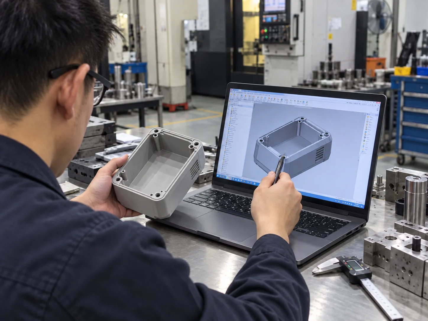
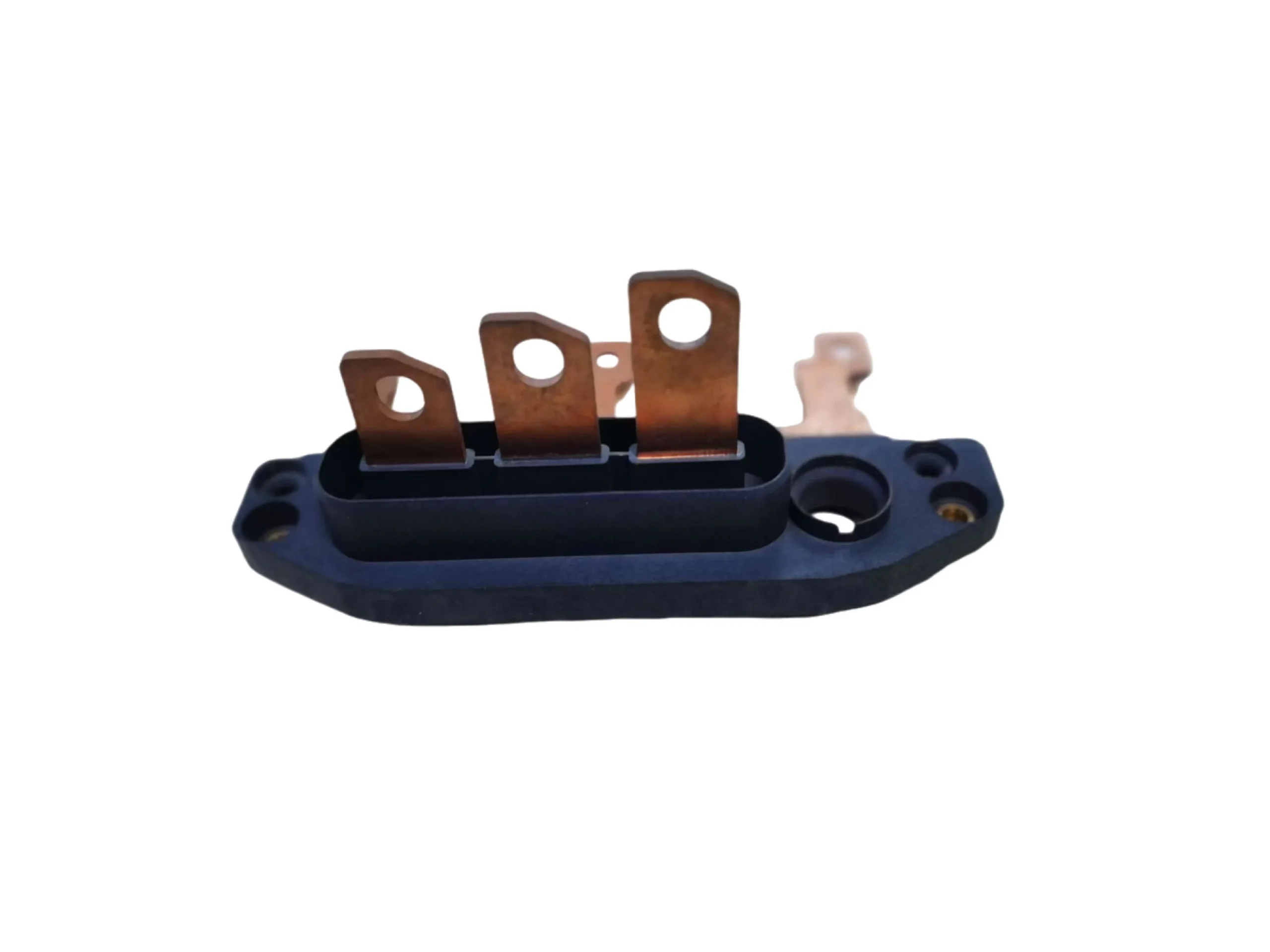
Robotic hardware commonly combines PCBs, sensors, cable harnesses, threaded inserts, bearings, motors, and multiple enclosure pieces. Assembly should make the correct condition easy and the incorrect condition difficult. Locating pins, asymmetric connectors, controlled wire channels, lead-ins, captive fasteners, and repeatable insert seats can reduce operator decisions. Metal threaded inserts can improve serviceability, but their position and surrounding wall structure should be designed for the selected installation or insert-molding method. Rapid prototyping is useful for testing access and assembly sequence before tooling.

7. Design for Tooling, Traceability, and Ramp-Up
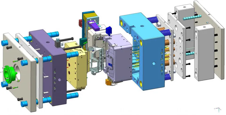
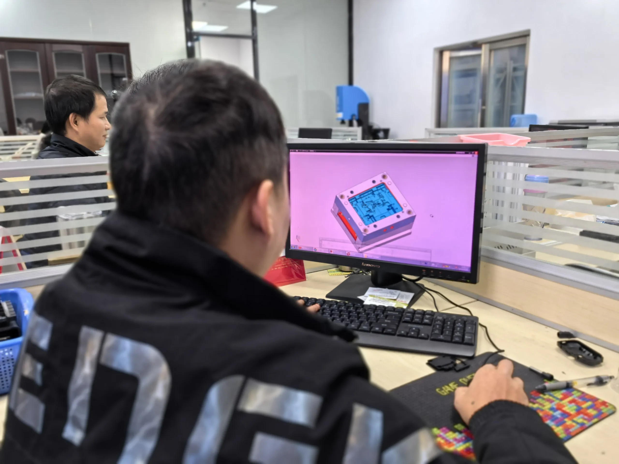
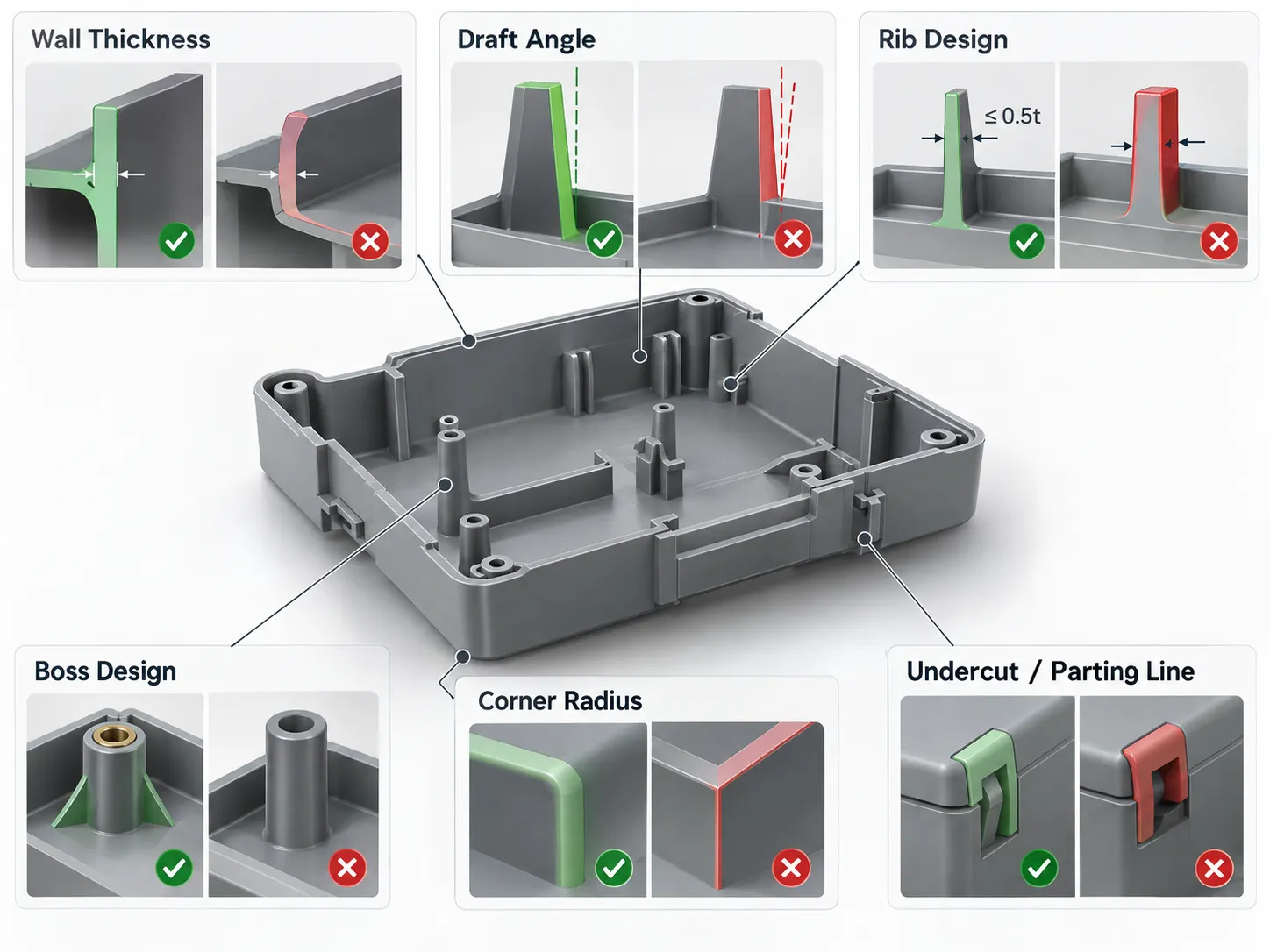
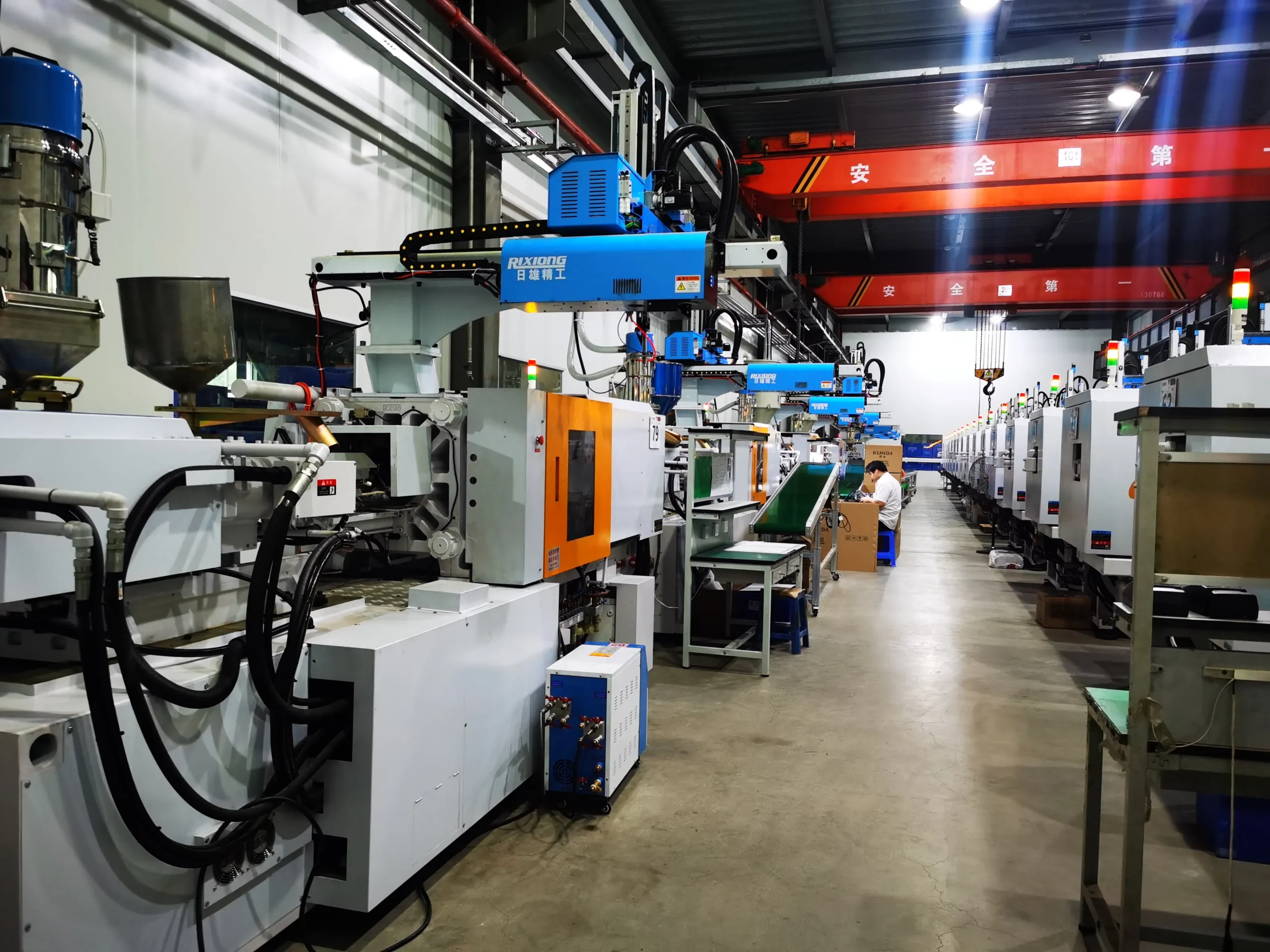
A robotics startup may begin with dozens of units and then need thousands quickly after qualification. The housing should therefore be designed with the future production process in mind even when early quantities are low. A formal DFM review can identify draft, undercuts, parting lines, gate positions, sink risk, and ejection strategy before mold design is released. During production, cavity identification, material-lot records, inspection data, and process traceability become more important when parts support safety-critical sensors or autonomous functions. Good geometry makes that scale-up easier rather than forcing a redesign at the moment demand increases.
Robotics AI Plastic Housing Design: From Prototype to Production
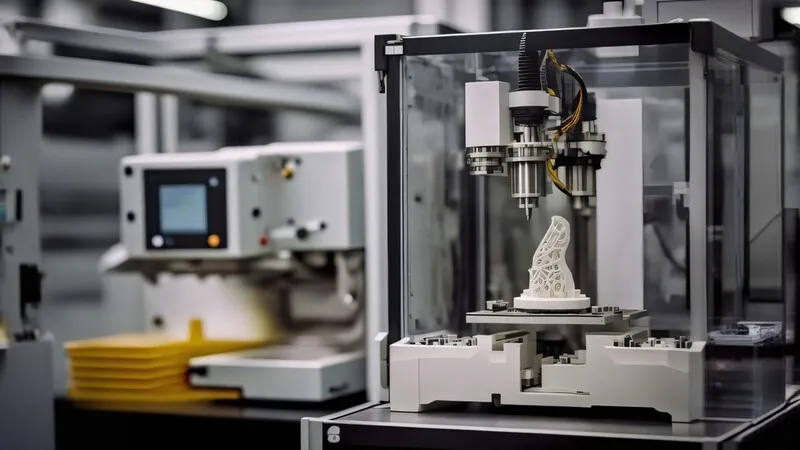
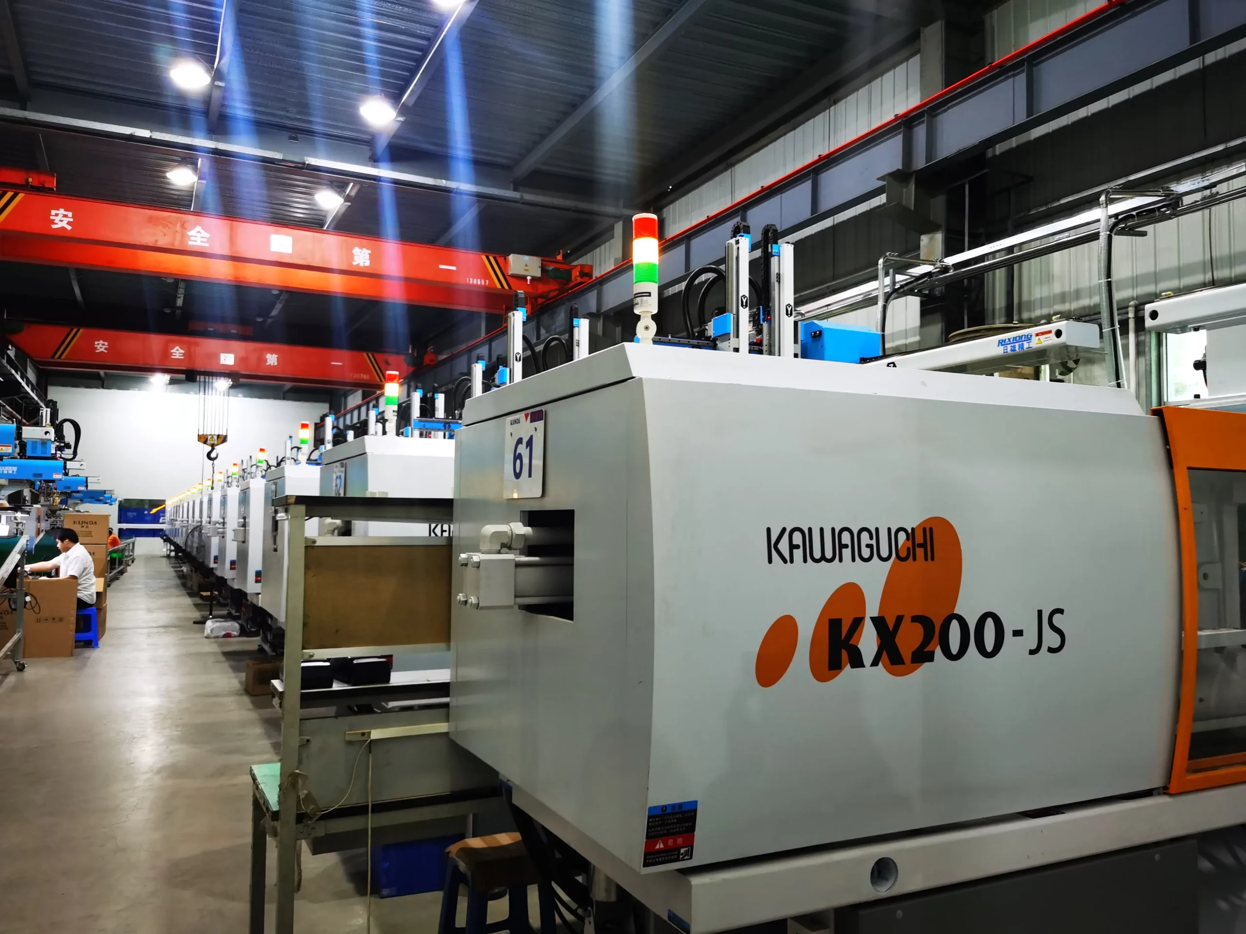
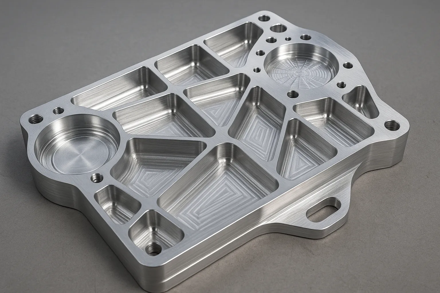
Robotics teams often iterate electronics and mechanics simultaneously, so the best manufacturing plan allows learning without losing control of configuration. Early printed housings can validate packaging and user interaction. CNC parts can support precision mechanical tests. Pilot molded parts then reveal true material shrinkage, surface quality, insert behavior, sealing consistency, and assembly variation. Once the design is stable, injection molding can provide the repeatability required for higher-volume robot and AI hardware programs.
Final Thoughts
A successful robotics enclosure is a mechanical subsystem, not a decorative cover. It must hold sensors in the right place, protect electronics, move efficiently, manage heat, support assembly, and survive the intended environment while remaining manufacturable at scale. Teams that address stiffness, alignment, sealing, thermal and EMI needs, materials, assembly, and production strategy together are less likely to discover mechanical limitations after the software and electronics are already mature. That integrated approach creates hardware that is easier to validate and easier to scale.